

contribution of MAR to the overall volumetric plasma recombination can reach
~40% [64].
Experimental data from both tokamaks [63, 65–68] and stellarators [69, 70] show
that in cold divertor plasma, the impurity radiation, in accordance with Eq. (9.14),
can also reduce the plasma flux to the targets.
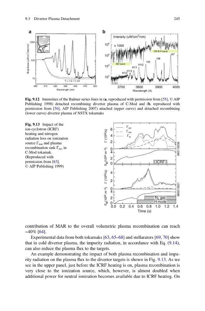
An example demonstrating the impact of both plasma recombination and impurity radiation on the plasma flux to the divertor targets is shown in Fig. 9.13. As we
see in the upper panel, just before the ICRF heating is on, plasma recombination is
very close to the ionization source, which, however, is almost doubled when
additional power for neutral ionization becomes available due to ICRF heating. On
1000
a
b
100
view
10
360
370
Brightness (mW/cm
2
/ster/nm)
380
390
T = 1.0–1.1 eV
Wavelength (nm)
400
410
420
10
6
10
5
10
4
10
3
3700
3800
3900
4000
Wavelength (A)
H13
H12
H11
H10
H9
H8
H7
CD B-X band
BD band
x 1000
Intensity (uW/cm
2
/nm)
120324
Fig. 9.12 Intensities of the Balmer series lines in (a, reproduced with permission from [55], © AIP
Publishing 1998) detached recombining divertor plasma of C-Mod and (b, reproduced with
permission from [56], AIP Publishing 2007) attached (upper curve) and detached recombining
(lower curve) divertor plasma of NSTX tokamaks
Time (s)
n –
e (10 20
m –3
)
Γ (10 22
/s)
0.0
0
2
4
0
980213021
980116038
2
4
n –
e (10 20
m –3
)
Γ (10 22
/s)
Γ ion
Γ rec
Γ w
0
2
4
0
2
6
4
0.2 0.4 0.6 0.8 1.0 1.2 1.4
ICRF
N 2 gas
H-mode
Fig. 9.13 Impact of the
ion-cyclotron (ICRF)
heating and nitrogen
radiation loss on ionization
source Γ ion and plasma
recombination sink Γ rec in
C-Mod tokamak.
(Reproduced with
permission from [63],
© AIP Publishing 1999)
9.3 Divertor Plasma Detachment
245
~40% [64].
Experimental data from both tokamaks [63, 65–68] and stellarators [69, 70] show
that in cold divertor plasma, the impurity radiation, in accordance with Eq. (9.14),
can also reduce the plasma flux to the targets.
An example demonstrating the impact of both plasma recombination and impurity radiation on the plasma flux to the divertor targets is shown in Fig. 9.13. As we
see in the upper panel, just before the ICRF heating is on, plasma recombination is
very close to the ionization source, which, however, is almost doubled when
additional power for neutral ionization becomes available due to ICRF heating. On
1000
a
b
100
view
10
360
370
Brightness (mW/cm
2
/ster/nm)
380
390
T = 1.0–1.1 eV
Wavelength (nm)
400
410
420
10
6
10
5
10
4
10
3
3700
3800
3900
4000
Wavelength (A)
H13
H12
H11
H10
H9
H8
H7
CD B-X band
BD band
x 1000
Intensity (uW/cm
2
/nm)
120324
Fig. 9.12 Intensities of the Balmer series lines in (a, reproduced with permission from [55], © AIP
Publishing 1998) detached recombining divertor plasma of C-Mod and (b, reproduced with
permission from [56], AIP Publishing 2007) attached (upper curve) and detached recombining
(lower curve) divertor plasma of NSTX tokamaks
Time (s)
n –
e (10 20
m –3
)
Γ (10 22
/s)
0.0
0
2
4
0
980213021
980116038
2
4
n –
e (10 20
m –3
)
Γ (10 22
/s)
Γ ion
Γ rec
Γ w
0
2
4
0
2
6
4
0.2 0.4 0.6 0.8 1.0 1.2 1.4
ICRF
N 2 gas
H-mode
Fig. 9.13 Impact of the
ion-cyclotron (ICRF)
heating and nitrogen
radiation loss on ionization
source Γ ion and plasma
recombination sink Γ rec in
C-Mod tokamak.
(Reproduced with
permission from [63],
© AIP Publishing 1999)
9.3 Divertor Plasma Detachment
245