

rectangle corresponding to the targets and two others where the plasma fluxes only
have the component normal to the magnetic field. This simplification can be justified
for modeling plasma interaction with the targets since most of the power going
through the SOL is concentrated in a narrow layer just outside the separatrix [6, 7],
which is not strongly affected by interaction with the side walls. However, when the
plasma profiles near, or fluxes onto the sidewall come into question, the grid needs to
be extended to cover the whole chamber. Grids of this kind are implemented in the
SOLEDGE2D-Eirene [8] and SOLPS [9] code packages, but they are not used
widely yet.
8.1.2 Parallel Transport
Plasma transport along the magnetic field is usually described with Braginckii-type
[11] terms which are valid if the ratio, γ, of the Coulomb mean-free path λ C of the
charged particles to the scale length L of variation of the plasma parameters along the
field line is small. However, the validity of the expressions for the high order
moments of the distribution functions, e.g. those describing the heat fluxes, requires
this parameter to be really small, γ < 10
À2 (see Sect. 6.4), which in practice does not
H
C
a
b
c
G
D
E
F
X
B
B
A
FG
H
GF
X
X
C
D
E
C
H
G
X
D
E
F
G
X
B
A
F
A
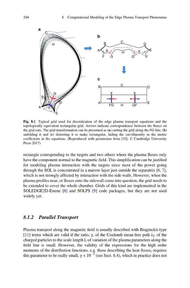
Fig. 8.1 Typical grid used for discretization of the edge plasma transport equations and the
topologically equivalent rectangular grid. Arrows indicate correspondence between the fluxes on
the grid cuts. The grid transformation can be presented as (a) cutting the grid along the FG line, (b)
unfolding it and (c) distorting it to make rectangular, hiding the curvilinearity in the metric
coefficients in the equations. (Reproduced with permission from [10], © Cambridge University
Press 2017)
204
8 Computational Modeling of the Edge Plasma Transport Phenomena
have the component normal to the magnetic field. This simplification can be justified
for modeling plasma interaction with the targets since most of the power going
through the SOL is concentrated in a narrow layer just outside the separatrix [6, 7],
which is not strongly affected by interaction with the side walls. However, when the
plasma profiles near, or fluxes onto the sidewall come into question, the grid needs to
be extended to cover the whole chamber. Grids of this kind are implemented in the
SOLEDGE2D-Eirene [8] and SOLPS [9] code packages, but they are not used
widely yet.
8.1.2 Parallel Transport
Plasma transport along the magnetic field is usually described with Braginckii-type
[11] terms which are valid if the ratio, γ, of the Coulomb mean-free path λ C of the
charged particles to the scale length L of variation of the plasma parameters along the
field line is small. However, the validity of the expressions for the high order
moments of the distribution functions, e.g. those describing the heat fluxes, requires
this parameter to be really small, γ < 10
À2 (see Sect. 6.4), which in practice does not
H
C
a
b
c
G
D
E
F
X
B
B
A
FG
H
GF
X
X
C
D
E
C
H
G
X
D
E
F
G
X
B
A
F
A
Fig. 8.1 Typical grid used for discretization of the edge plasma transport equations and the
topologically equivalent rectangular grid. Arrows indicate correspondence between the fluxes on
the grid cuts. The grid transformation can be presented as (a) cutting the grid along the FG line, (b)
unfolding it and (c) distorting it to make rectangular, hiding the curvilinearity in the metric
coefficients in the equations. (Reproduced with permission from [10], © Cambridge University
Press 2017)
204
8 Computational Modeling of the Edge Plasma Transport Phenomena