

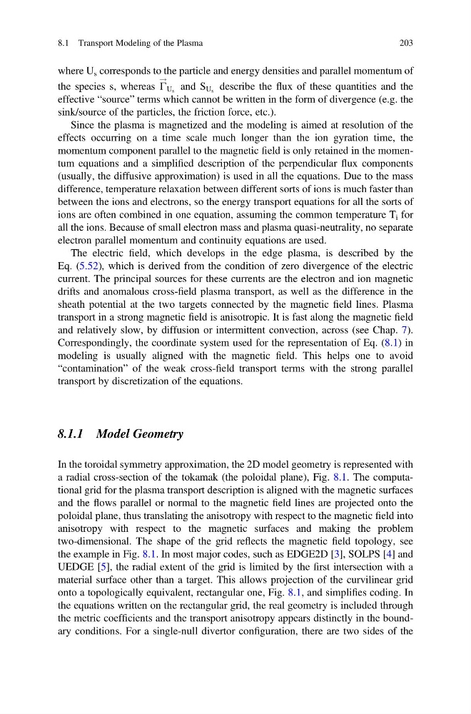
where U s corresponds to the particle and energy densities and parallel momentum of
the species s, whereas Γ
!
U s and S U s describe the flux of these quantities and the
effective “source” terms which cannot be written in the form of divergence (e.g. the
sink/source of the particles, the friction force, etc.).
Since the plasma is magnetized and the modeling is aimed at resolution of the
effects occurring on a time scale much longer than the ion gyration time, the
momentum component parallel to the magnetic field is only retained in the momentum equations and a simplified description of the perpendicular flux components
(usually, the diffusive approximation) is used in all the equations. Due to the mass
difference, temperature relaxation between different sorts of ions is much faster than
between the ions and electrons, so the energy transport equations for all the sorts of
ions are often combined in one equation, assuming the common temperature T i for
all the ions. Because of small electron mass and plasma quasi-neutrality, no separate
electron parallel momentum and continuity equations are used.
The electric field, which develops in the edge plasma, is described by the
Eq. (5.52), which is derived from the condition of zero divergence of the electric
current. The principal sources for these currents are the electron and ion magnetic
drifts and anomalous cross-field plasma transport, as well as the difference in the
sheath potential at the two targets connected by the magnetic field lines. Plasma
transport in a strong magnetic field is anisotropic. It is fast along the magnetic field
and relatively slow, by diffusion or intermittent convection, across (see Chap. 7).
Correspondingly, the coordinate system used for the representation of Eq. (8.1) in
modeling is usually aligned with the magnetic field. This helps one to avoid
“contamination” of the weak cross-field transport terms with the strong parallel
transport by discretization of the equations.
8.1.1 Model Geometry
In the toroidal symmetry approximation, the 2D model geometry is represented with
a radial cross-section of the tokamak (the poloidal plane), Fig. 8.1. The computational grid for the plasma transport description is aligned with the magnetic surfaces
and the flows parallel or normal to the magnetic field lines are projected onto the
poloidal plane, thus translating the anisotropy with respect to the magnetic field into
anisotropy with respect to the magnetic surfaces and making the problem
two-dimensional. The shape of the grid reflects the magnetic field topology, see
the example in Fig. 8.1. In most major codes, such as EDGE2D [3], SOLPS [4] and
UEDGE [5], the radial extent of the grid is limited by the first intersection with a
material surface other than a target. This allows projection of the curvilinear grid
onto a topologically equivalent, rectangular one, Fig. 8.1, and simplifies coding. In
the equations written on the rectangular grid, the real geometry is included through
the metric coefficients and the transport anisotropy appears distinctly in the boundary conditions. For a single-null divertor configuration, there are two sides of the
8.1 Transport Modeling of the Plasma
203
the species s, whereas Γ
!
U s and S U s describe the flux of these quantities and the
effective “source” terms which cannot be written in the form of divergence (e.g. the
sink/source of the particles, the friction force, etc.).
Since the plasma is magnetized and the modeling is aimed at resolution of the
effects occurring on a time scale much longer than the ion gyration time, the
momentum component parallel to the magnetic field is only retained in the momentum equations and a simplified description of the perpendicular flux components
(usually, the diffusive approximation) is used in all the equations. Due to the mass
difference, temperature relaxation between different sorts of ions is much faster than
between the ions and electrons, so the energy transport equations for all the sorts of
ions are often combined in one equation, assuming the common temperature T i for
all the ions. Because of small electron mass and plasma quasi-neutrality, no separate
electron parallel momentum and continuity equations are used.
The electric field, which develops in the edge plasma, is described by the
Eq. (5.52), which is derived from the condition of zero divergence of the electric
current. The principal sources for these currents are the electron and ion magnetic
drifts and anomalous cross-field plasma transport, as well as the difference in the
sheath potential at the two targets connected by the magnetic field lines. Plasma
transport in a strong magnetic field is anisotropic. It is fast along the magnetic field
and relatively slow, by diffusion or intermittent convection, across (see Chap. 7).
Correspondingly, the coordinate system used for the representation of Eq. (8.1) in
modeling is usually aligned with the magnetic field. This helps one to avoid
“contamination” of the weak cross-field transport terms with the strong parallel
transport by discretization of the equations.
8.1.1 Model Geometry
In the toroidal symmetry approximation, the 2D model geometry is represented with
a radial cross-section of the tokamak (the poloidal plane), Fig. 8.1. The computational grid for the plasma transport description is aligned with the magnetic surfaces
and the flows parallel or normal to the magnetic field lines are projected onto the
poloidal plane, thus translating the anisotropy with respect to the magnetic field into
anisotropy with respect to the magnetic surfaces and making the problem
two-dimensional. The shape of the grid reflects the magnetic field topology, see
the example in Fig. 8.1. In most major codes, such as EDGE2D [3], SOLPS [4] and
UEDGE [5], the radial extent of the grid is limited by the first intersection with a
material surface other than a target. This allows projection of the curvilinear grid
onto a topologically equivalent, rectangular one, Fig. 8.1, and simplifies coding. In
the equations written on the rectangular grid, the real geometry is included through
the metric coefficients and the transport anisotropy appears distinctly in the boundary conditions. For a single-null divertor configuration, there are two sides of the
8.1 Transport Modeling of the Plasma
203