

74
3 Analysis of Strain
3.16 Measurement of Surface Strains—Strain Rosettes
3.16.1 Strain Rosettes
Whenever a material is subjected to plane stress, it is desirable to obtain the stresses
by direct measurement. As the stresses cannot be measured directly, it is essential to
measure the strains or deformations that take place in the material during loading.
These strains or deformations are measured with sensitive strain gauges attached to
the surface of the body before it is loaded so that these gauges can record the amount
of strain that takes place during loading.
It is more accurate and easier to measure in the neighbourhood of a chosen point
on the surface of the body, the linear strains in different directions and then computes
from these measurements the magnitudes and directions of the principal strains. Such
a group of strain gauges is called a “strain rosette”.
3.16.2 Strain Transformation Laws
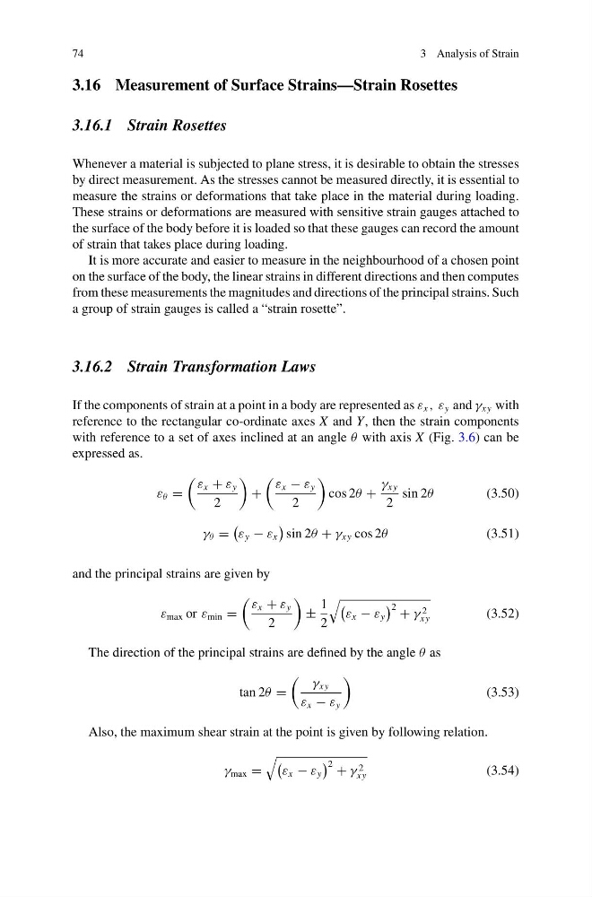
If the components of strain at a point in a body are represented as ε x , ε y and γ xy with
reference to the rectangular co-ordinate axes X and Y, then the strain components
with reference to a set of axes inclined at an angle θ with axis X (Fig. 3.6) can be
expressed as.
ε θ =
ε x + ε y
2
+
ε x − ε y
2
cos 2θ +
γ xy
2
sin 2θ
(3.50)
γ θ =
ε y − ε x
sin 2θ + γ xy cos 2θ
(3.51)
and the principal strains are given by
ε max or ε min =
ε x + ε y
2
±
1
2
ε x − ε y
2 + γ 2
xy
(3.52)
The direction of the principal strains are defined by the angle θ as
tan 2θ =
γ xy
ε x − ε y
(3.53)
Also, the maximum shear strain at the point is given by following relation.
γ max =
ε x − ε y
2 + γ 2
xy
(3.54)
3 Analysis of Strain
3.16 Measurement of Surface Strains—Strain Rosettes
3.16.1 Strain Rosettes
Whenever a material is subjected to plane stress, it is desirable to obtain the stresses
by direct measurement. As the stresses cannot be measured directly, it is essential to
measure the strains or deformations that take place in the material during loading.
These strains or deformations are measured with sensitive strain gauges attached to
the surface of the body before it is loaded so that these gauges can record the amount
of strain that takes place during loading.
It is more accurate and easier to measure in the neighbourhood of a chosen point
on the surface of the body, the linear strains in different directions and then computes
from these measurements the magnitudes and directions of the principal strains. Such
a group of strain gauges is called a “strain rosette”.
3.16.2 Strain Transformation Laws
If the components of strain at a point in a body are represented as ε x , ε y and γ xy with
reference to the rectangular co-ordinate axes X and Y, then the strain components
with reference to a set of axes inclined at an angle θ with axis X (Fig. 3.6) can be
expressed as.
ε θ =
ε x + ε y
2
+
ε x − ε y
2
cos 2θ +
γ xy
2
sin 2θ
(3.50)
γ θ =
ε y − ε x
sin 2θ + γ xy cos 2θ
(3.51)
and the principal strains are given by
ε max or ε min =
ε x + ε y
2
±
1
2
ε x − ε y
2 + γ 2
xy
(3.52)
The direction of the principal strains are defined by the angle θ as
tan 2θ =
γ xy
ε x − ε y
(3.53)
Also, the maximum shear strain at the point is given by following relation.
γ max =
ε x − ε y
2 + γ 2
xy
(3.54)