

38
2 Analysis of Stress
τ max = ±
1
4
(55.2 − 27.6) 2 + (20.7) 2
= ±24.9 MPa
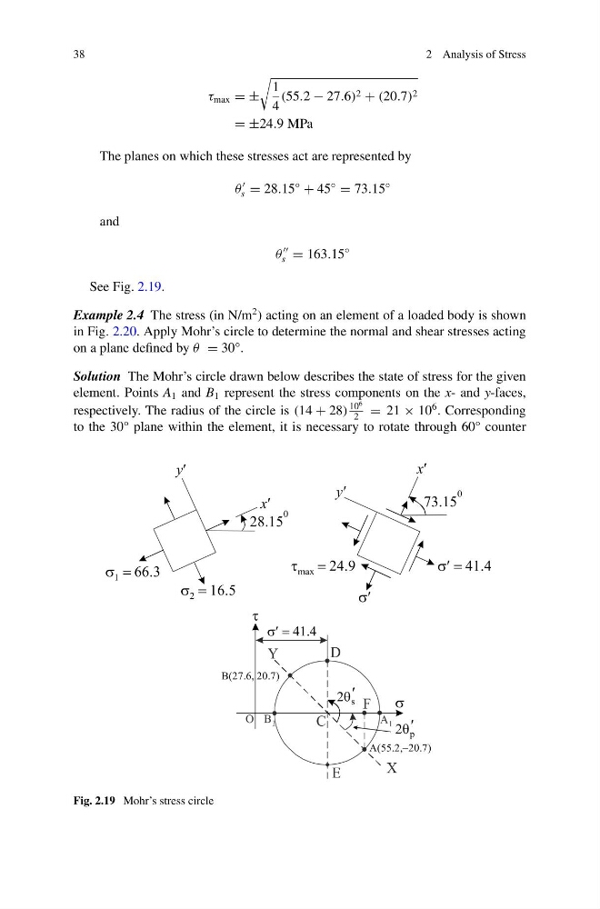
The planes on which these stresses act are represented by
θ
s = 28.15
◦
+ 45
◦
= 73.15
◦
and
θ
s = 163.15
◦
See Fig. 2.19.
Example 2.4 The stress (in N/m
2 ) acting on an element of a loaded body is shown
in Fig. 2.20. Apply Mohr’s circle to determine the normal and shear stresses acting
on a plane defined by θ = 30°.
Solution The Mohr’s circle drawn below describes the state of stress for the given
element. Points A 1 and B 1 represent the stress components on the x- and y-faces,
respectively. The radius of the circle is (14 + 28)
10
6
2
= 21 × 10
6 . Corresponding
to the 30° plane within the element, it is necessary to rotate through 60° counter
Fig. 2.19 Mohr’s stress circle
2 Analysis of Stress
τ max = ±
1
4
(55.2 − 27.6) 2 + (20.7) 2
= ±24.9 MPa
The planes on which these stresses act are represented by
θ
s = 28.15
◦
+ 45
◦
= 73.15
◦
and
θ
s = 163.15
◦
See Fig. 2.19.
Example 2.4 The stress (in N/m
2 ) acting on an element of a loaded body is shown
in Fig. 2.20. Apply Mohr’s circle to determine the normal and shear stresses acting
on a plane defined by θ = 30°.
Solution The Mohr’s circle drawn below describes the state of stress for the given
element. Points A 1 and B 1 represent the stress components on the x- and y-faces,
respectively. The radius of the circle is (14 + 28)
10
6
2
= 21 × 10
6 . Corresponding
to the 30° plane within the element, it is necessary to rotate through 60° counter
Fig. 2.19 Mohr’s stress circle