

2.23 Numerical Examples
37
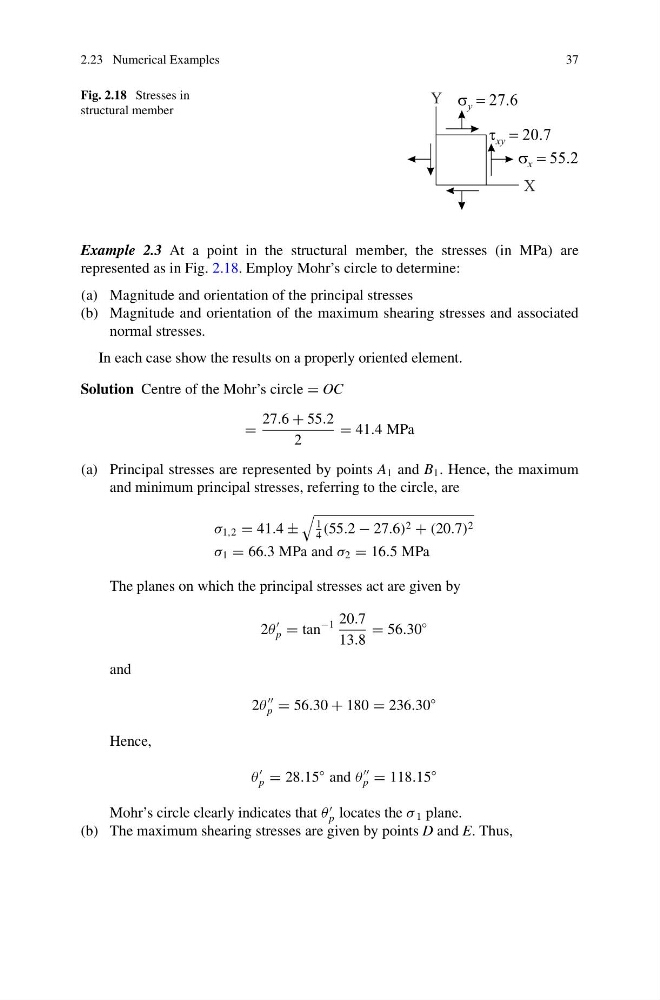
Fig. 2.18 Stresses in
structural member
Example 2.3 At a point in the structural member, the stresses (in MPa) are
represented as in Fig. 2.18. Employ Mohr’s circle to determine:
(a) Magnitude and orientation of the principal stresses
(b) Magnitude and orientation of the maximum shearing stresses and associated
normal stresses.
In each case show the results on a properly oriented element.
Solution Centre of the Mohr’s circle = OC
=
27.6 + 55.2
2
= 41.4 MPa
(a) Principal stresses are represented by points A 1 and B 1 . Hence, the maximum
and minimum principal stresses, referring to the circle, are
σ 1,2 = 41.4 ±
1
4
(55.2 − 27.6) 2 + (20.7) 2
σ 1 = 66.3 MPa and σ 2 = 16.5 MPa
The planes on which the principal stresses act are given by
2θ
p = tan
−1 20.7
13.8
= 56.30
◦
and
2θ
p = 56.30 + 180 = 236.30
◦
Hence,
θ
p = 28.15
◦ and θ
p = 118.15
◦
Mohr’s circle clearly indicates that θ
p locates the σ 1 plane.
(b) The maximum shearing stresses are given by points D and E. Thus,
37
Fig. 2.18 Stresses in
structural member
Example 2.3 At a point in the structural member, the stresses (in MPa) are
represented as in Fig. 2.18. Employ Mohr’s circle to determine:
(a) Magnitude and orientation of the principal stresses
(b) Magnitude and orientation of the maximum shearing stresses and associated
normal stresses.
In each case show the results on a properly oriented element.
Solution Centre of the Mohr’s circle = OC
=
27.6 + 55.2
2
= 41.4 MPa
(a) Principal stresses are represented by points A 1 and B 1 . Hence, the maximum
and minimum principal stresses, referring to the circle, are
σ 1,2 = 41.4 ±
1
4
(55.2 − 27.6) 2 + (20.7) 2
σ 1 = 66.3 MPa and σ 2 = 16.5 MPa
The planes on which the principal stresses act are given by
2θ
p = tan
−1 20.7
13.8
= 56.30
◦
and
2θ
p = 56.30 + 180 = 236.30
◦
Hence,
θ
p = 28.15
◦ and θ
p = 118.15
◦
Mohr’s circle clearly indicates that θ
p locates the σ 1 plane.
(b) The maximum shearing stresses are given by points D and E. Thus,