

72
3 Subsonic Wind Tunnels
changeable with three different test sections (all of the same height 2.35 m and width
1.15 m, 2.25 m or 3.6 m) in order to best adapt to model size, speed, cloud cover
and flow uniformity. Each configuration can be used for both aerodynamic and icing
experiments by interchanging the turbulence filter module and the module generating
the icing cloud.
The IWT test section, in particular the distance between the cloud generation
section (spray boom) and the model stagnation region where accretion occurs, was
dimensioned in order to realise the thermal equilibrium rather than the quality of
the flow. The fan, including its motor, is located in the return leg of the circuit. The
diameter of the fan is 3.9 m, its maximum rotation speed being 750 rpm driven by a
4 MW motor. The fan is designed to generate a maximum speed of 225 m/s in the
smallest section.
A special cooling station equipped with 4 compressors with a total cooling capacity of 6.4 MW achieves a minimum temperature of −40 °C in the smallest high-speed
section and −32 °C in the other sections. The IWT has the unique feature for an
installation of its size to simulate the pressure at an altitude of 7000 m, which can
reproduce the actual flight conditions. This possibility is also very useful for studies
of similarity laws for icing and for evaluating the influence of altitude on the shape
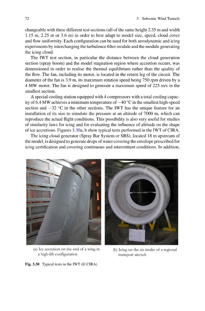
of ice accretions. Figures 3.30a, b show typical tests performed in the IWT of CIRA.
The icing cloud generator (Spray Bar System or SBS), located 18 m upstream of
the model, is designed to generate drops of water covering the envelope prescribed for
icing certification and covering continuous and intermittent conditions. In addition,
a high-lift configuration
(a) Ice accretion on the end of a wing in
transport aircraft
(b) Icing on the air intake of a regional
Fig. 3.30 Typical tests in the IWT (© CIRA)
3 Subsonic Wind Tunnels
changeable with three different test sections (all of the same height 2.35 m and width
1.15 m, 2.25 m or 3.6 m) in order to best adapt to model size, speed, cloud cover
and flow uniformity. Each configuration can be used for both aerodynamic and icing
experiments by interchanging the turbulence filter module and the module generating
the icing cloud.
The IWT test section, in particular the distance between the cloud generation
section (spray boom) and the model stagnation region where accretion occurs, was
dimensioned in order to realise the thermal equilibrium rather than the quality of
the flow. The fan, including its motor, is located in the return leg of the circuit. The
diameter of the fan is 3.9 m, its maximum rotation speed being 750 rpm driven by a
4 MW motor. The fan is designed to generate a maximum speed of 225 m/s in the
smallest section.
A special cooling station equipped with 4 compressors with a total cooling capacity of 6.4 MW achieves a minimum temperature of −40 °C in the smallest high-speed
section and −32 °C in the other sections. The IWT has the unique feature for an
installation of its size to simulate the pressure at an altitude of 7000 m, which can
reproduce the actual flight conditions. This possibility is also very useful for studies
of similarity laws for icing and for evaluating the influence of altitude on the shape
of ice accretions. Figures 3.30a, b show typical tests performed in the IWT of CIRA.
The icing cloud generator (Spray Bar System or SBS), located 18 m upstream of
the model, is designed to generate drops of water covering the envelope prescribed for
icing certification and covering continuous and intermittent conditions. In addition,
a high-lift configuration
(a) Ice accretion on the end of a wing in
transport aircraft
(b) Icing on the air intake of a regional
Fig. 3.30 Typical tests in the IWT (© CIRA)