

2.7 Design and Manufacturing of Wind Tunnel Models
49
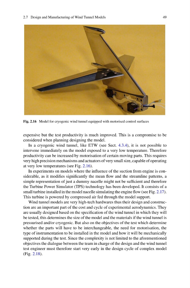
Fig. 2.16 Model for cryogenic wind tunnel equipped with motorised control surfaces
expensive but the test productivity is much improved. This is a compromise to be
considered when planning designing the model.
In a cryogenic wind tunnel, like ETW (see Sect. 4.3.4), it is not possible to
intervene immediately on the model exposed to a very low temperature. Therefore
productivity can be increased by motorisation of certain moving parts. This requires
very high precision mechanisms and actuators of very small size, capable of operating
at very low temperatures (see Fig. 2.16).
In experiments on models where the influence of the suction from engine is considerable, as it modifies significantly the mean flow and the streamline patterns, a
simple representation of just a dummy nacelle might not be sufficient and therefore
the Turbine Power Simulator (TPS) technology has been developed. It consists of a
small turbine installed in the model nacelle simulating the engine flow (see Fig. 2.17).
This turbine is powered by compressed air fed through the model support.
Wind tunnel models are very high-tech hardwares thus their design and construction are an important part of the cost and cycle of experimental aerodynamics. They
are usually designed based on the specification of the wind tunnel in which they will
be tested, this determines the size of the model and the materials if the wind tunnel is
pressurised and/or cryogenic. But also on the objectives of the test which determine
whether the parts will have to be interchangeable, the need for motorisation, the
type of instrumentation to be installed in the model and how it will be mechanically
supported during the test. Since the complexity is not limited to the aforementioned
objectives the dialogue between the team in charge of the design and the wind tunnel
test engineer must therefore start very early in the design cycle of complex model
(Fig. 2.18).
49
Fig. 2.16 Model for cryogenic wind tunnel equipped with motorised control surfaces
expensive but the test productivity is much improved. This is a compromise to be
considered when planning designing the model.
In a cryogenic wind tunnel, like ETW (see Sect. 4.3.4), it is not possible to
intervene immediately on the model exposed to a very low temperature. Therefore
productivity can be increased by motorisation of certain moving parts. This requires
very high precision mechanisms and actuators of very small size, capable of operating
at very low temperatures (see Fig. 2.16).
In experiments on models where the influence of the suction from engine is considerable, as it modifies significantly the mean flow and the streamline patterns, a
simple representation of just a dummy nacelle might not be sufficient and therefore
the Turbine Power Simulator (TPS) technology has been developed. It consists of a
small turbine installed in the model nacelle simulating the engine flow (see Fig. 2.17).
This turbine is powered by compressed air fed through the model support.
Wind tunnel models are very high-tech hardwares thus their design and construction are an important part of the cost and cycle of experimental aerodynamics. They
are usually designed based on the specification of the wind tunnel in which they will
be tested, this determines the size of the model and the materials if the wind tunnel is
pressurised and/or cryogenic. But also on the objectives of the test which determine
whether the parts will have to be interchangeable, the need for motorisation, the
type of instrumentation to be installed in the model and how it will be mechanically
supported during the test. Since the complexity is not limited to the aforementioned
objectives the dialogue between the team in charge of the design and the wind tunnel
test engineer must therefore start very early in the design cycle of complex model
(Fig. 2.18).