

36
2 Wind Tunnels and Other Aerodynamic Test Facilities
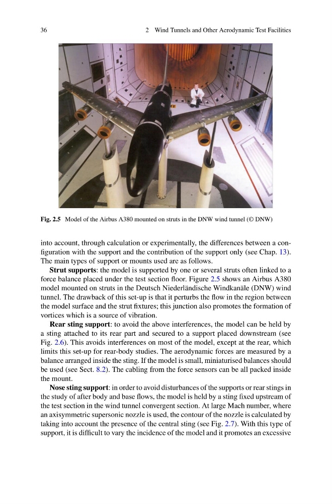
Fig. 2.5 Model of the Airbus A380 mounted on struts in the DNW wind tunnel (© DNW)
into account, through calculation or experimentally, the differences between a configuration with the support and the contribution of the support only (see Chap. 13).
The main types of support or mounts used are as follows.
Strut supports: the model is supported by one or several struts often linked to a
force balance placed under the test section floor. Figure 2.5 shows an Airbus A380
model mounted on struts in the Deutsch Niederländische Windkanäle (DNW) wind
tunnel. The drawback of this set-up is that it perturbs the flow in the region between
the model surface and the strut fixtures; this junction also promotes the formation of
vortices which is a source of vibration.
Rear sting support: to avoid the above interferences, the model can be held by
a sting attached to its rear part and secured to a support placed downstream (see
Fig. 2.6). This avoids interferences on most of the model, except at the rear, which
limits this set-up for rear-body studies. The aerodynamic forces are measured by a
balance arranged inside the sting. If the model is small, miniaturised balances should
be used (see Sect. 8.2). The cabling from the force sensors can be all packed inside
the mount.
Nose sting support: in order to avoid disturbances of the supports or rear stings in
the study of after body and base flows, the model is held by a sting fixed upstream of
the test section in the wind tunnel convergent section. At large Mach number, where
an axisymmetric supersonic nozzle is used, the contour of the nozzle is calculated by
taking into account the presence of the central sting (see Fig. 2.7). With this type of
support, it is difficult to vary the incidence of the model and it promotes an excessive
2 Wind Tunnels and Other Aerodynamic Test Facilities
Fig. 2.5 Model of the Airbus A380 mounted on struts in the DNW wind tunnel (© DNW)
into account, through calculation or experimentally, the differences between a configuration with the support and the contribution of the support only (see Chap. 13).
The main types of support or mounts used are as follows.
Strut supports: the model is supported by one or several struts often linked to a
force balance placed under the test section floor. Figure 2.5 shows an Airbus A380
model mounted on struts in the Deutsch Niederländische Windkanäle (DNW) wind
tunnel. The drawback of this set-up is that it perturbs the flow in the region between
the model surface and the strut fixtures; this junction also promotes the formation of
vortices which is a source of vibration.
Rear sting support: to avoid the above interferences, the model can be held by
a sting attached to its rear part and secured to a support placed downstream (see
Fig. 2.6). This avoids interferences on most of the model, except at the rear, which
limits this set-up for rear-body studies. The aerodynamic forces are measured by a
balance arranged inside the sting. If the model is small, miniaturised balances should
be used (see Sect. 8.2). The cabling from the force sensors can be all packed inside
the mount.
Nose sting support: in order to avoid disturbances of the supports or rear stings in
the study of after body and base flows, the model is held by a sting fixed upstream of
the test section in the wind tunnel convergent section. At large Mach number, where
an axisymmetric supersonic nozzle is used, the contour of the nozzle is calculated by
taking into account the presence of the central sting (see Fig. 2.7). With this type of
support, it is difficult to vary the incidence of the model and it promotes an excessive