

20
1 The Experimental Approach in Aerodynamic Design
of calibre ranging from 20 to 105 mm. The launch Mach number, depending on the
configurations studied is between 0.6 and 6.0.
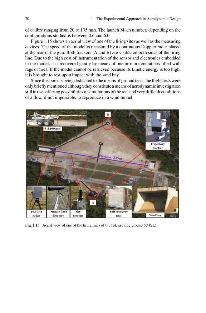
Figure 1.15 shows an aerial view of one of the firing sites as well as the measuring
devices. The speed of the model is measured by a continuous Doppler radar placed
at the rear of the gun. Both trackers (A and B) are visible on both sides of the firing
line. Due to the high cost of instrumentation of the sensor and electronics embedded
in the model, it is recovered gently by means of one or more containers filled with
rags or tires. If the model cannot be retrieved because its kinetic energy is too high,
it is brought to rest upon impact with the sand bay.
Since this book is being dedicated to the means of ground tests, the flight tests were
only briefly mentioned although they constitute a means of aerodynamic investigation
still in use, offering possibilities of simulations of the real and very difficult conditions
of a flow, if not impossible, to reproduce in a wind tunnel.
Fig. 1.15 Aerial view of one of the firing lines of the ISL proving ground (© ISL)
1 The Experimental Approach in Aerodynamic Design
of calibre ranging from 20 to 105 mm. The launch Mach number, depending on the
configurations studied is between 0.6 and 6.0.
Figure 1.15 shows an aerial view of one of the firing sites as well as the measuring
devices. The speed of the model is measured by a continuous Doppler radar placed
at the rear of the gun. Both trackers (A and B) are visible on both sides of the firing
line. Due to the high cost of instrumentation of the sensor and electronics embedded
in the model, it is recovered gently by means of one or more containers filled with
rags or tires. If the model cannot be retrieved because its kinetic energy is too high,
it is brought to rest upon impact with the sand bay.
Since this book is being dedicated to the means of ground tests, the flight tests were
only briefly mentioned although they constitute a means of aerodynamic investigation
still in use, offering possibilities of simulations of the real and very difficult conditions
of a flow, if not impossible, to reproduce in a wind tunnel.
Fig. 1.15 Aerial view of one of the firing lines of the ISL proving ground (© ISL)