

1.7 Flight Tests
15
1.7 Flight Tests
1.7.1 Flight Test Beds
Here, we do not consider flight tests intended to test the performance of a new aircraft
and to define its flight range prior to delivery to the airliner, but experiments where
the aircraft is used as a flying test bed to carry out experiments in conditions closer to
reality rather than those achievable in a constrained wind tunnel. This has the benefit
of reproducing the Reynolds number and the very low freestream turbulence which
is primordial for testing the techniques for drag reduction, such as natural or hybrid
laminar flow control. We will see in Chap. 2 and Sect. 5.4 that the flows produced
in the wind tunnels are affected by environmental or freestream disturbances which
are very difficult to eliminate. This can lead to unreliable experimental results due to
premature laminar to turbulent transition and also potential misinterpretation of the
result during the design phase culminating in more severe consequences.
Below are examples of two studies employing an aircraft as a flying test bed.
They are both for the study of transition to turbulence on wings a key motivation for
this study being skin friction drag reduction in the search for energy savings. The
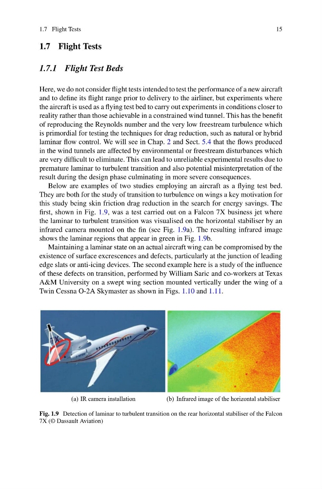
first, shown in Fig. 1.9, was a test carried out on a Falcon 7X business jet where
the laminar to turbulent transition was visualised on the horizontal stabiliser by an
infrared camera mounted on the fin (see Fig. 1.9a). The resulting infrared image
shows the laminar regions that appear in green in Fig. 1.9b.
Maintaining a laminar state on an actual aircraft wing can be compromised by the
existence of surface excrescences and defects, particularly at the junction of leading
edge slats or anti-icing devices. The second example here is a study of the influence
of these defects on transition, performed by William Saric and co-workers at Texas
A&M University on a swept wing section mounted vertically under the wing of a
Twin Cessna O-2A Skymaster as shown in Figs. 1.10 and 1.11.
(a) IR camera installation
(b) Infrared image of the horizontal stabiliser
Fig. 1.9 Detection of laminar to turbulent transition on the rear horizontal stabiliser of the Falcon
7X (© Dassault Aviation)
15
1.7 Flight Tests
1.7.1 Flight Test Beds
Here, we do not consider flight tests intended to test the performance of a new aircraft
and to define its flight range prior to delivery to the airliner, but experiments where
the aircraft is used as a flying test bed to carry out experiments in conditions closer to
reality rather than those achievable in a constrained wind tunnel. This has the benefit
of reproducing the Reynolds number and the very low freestream turbulence which
is primordial for testing the techniques for drag reduction, such as natural or hybrid
laminar flow control. We will see in Chap. 2 and Sect. 5.4 that the flows produced
in the wind tunnels are affected by environmental or freestream disturbances which
are very difficult to eliminate. This can lead to unreliable experimental results due to
premature laminar to turbulent transition and also potential misinterpretation of the
result during the design phase culminating in more severe consequences.
Below are examples of two studies employing an aircraft as a flying test bed.
They are both for the study of transition to turbulence on wings a key motivation for
this study being skin friction drag reduction in the search for energy savings. The
first, shown in Fig. 1.9, was a test carried out on a Falcon 7X business jet where
the laminar to turbulent transition was visualised on the horizontal stabiliser by an
infrared camera mounted on the fin (see Fig. 1.9a). The resulting infrared image
shows the laminar regions that appear in green in Fig. 1.9b.
Maintaining a laminar state on an actual aircraft wing can be compromised by the
existence of surface excrescences and defects, particularly at the junction of leading
edge slats or anti-icing devices. The second example here is a study of the influence
of these defects on transition, performed by William Saric and co-workers at Texas
A&M University on a swept wing section mounted vertically under the wing of a
Twin Cessna O-2A Skymaster as shown in Figs. 1.10 and 1.11.
(a) IR camera installation
(b) Infrared image of the horizontal stabiliser
Fig. 1.9 Detection of laminar to turbulent transition on the rear horizontal stabiliser of the Falcon
7X (© Dassault Aviation)