

186
8 Measurement of Aerodynamic Forces and Moments
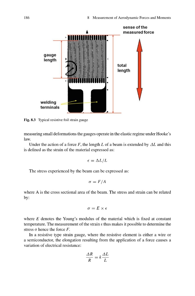
Fig. 8.3 Typical resistive foil strain gauge
measuring small deformations the gauges operate in the elastic regime under Hooke’s
law.
Under the action of a force F, the length L of a beam is extended by ΔL and this
is defined as the strain of the material expressed as:
= L/L
The stress experienced by the beam can be expressed as:
σ = F/A
where A is the cross sectional area of the beam. The stress and strain can be related
by:
σ = E ×
where E denotes the Young’s modulus of the material which is fixed at constant
temperature. The measurement of the strain ε thus makes it possible to determine the
stress σ hence the force F.
In a resistive type strain gauge, where the resistive element is either a wire or
a semiconductor, the elongation resulting from the application of a force causes a
variation of electrical resistance:
ΔR
R
= k
ΔL
L
8 Measurement of Aerodynamic Forces and Moments
Fig. 8.3 Typical resistive foil strain gauge
measuring small deformations the gauges operate in the elastic regime under Hooke’s
law.
Under the action of a force F, the length L of a beam is extended by ΔL and this
is defined as the strain of the material expressed as:
= L/L
The stress experienced by the beam can be expressed as:
σ = F/A
where A is the cross sectional area of the beam. The stress and strain can be related
by:
σ = E ×
where E denotes the Young’s modulus of the material which is fixed at constant
temperature. The measurement of the strain ε thus makes it possible to determine the
stress σ hence the force F.
In a resistive type strain gauge, where the resistive element is either a wire or
a semiconductor, the elongation resulting from the application of a force causes a
variation of electrical resistance:
ΔR
R
= k
ΔL
L