

8.1 The Aerodynamic Forces and Moments
185
In a similar way, the moment
− →
M is decomposed into:
– a component along
− →
X a → rolling moment M x ,
– a component along
− →
Z a → yawing moment M z ,
– a component according to
− →
Y a → pitching moment M y .
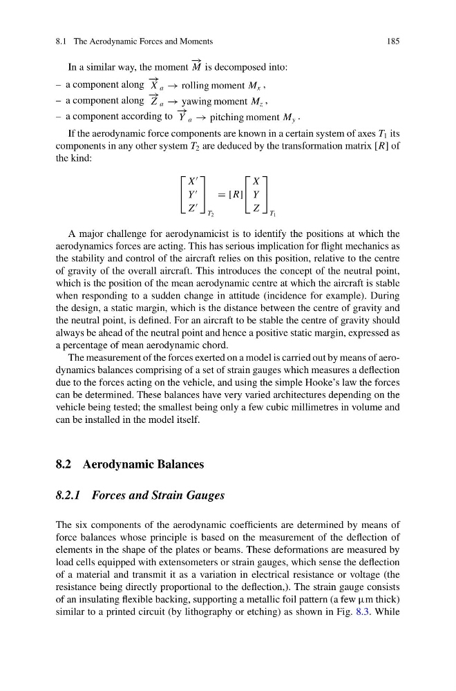
If the aerodynamic force components are known in a certain system of axes T 1 its
components in any other system T 2 are deduced by the transformation matrix [R] of
the kind:
⎡
⎣
X
Y
Z
⎤
⎦
T 2
= [R]
⎡
⎣
X
Y
Z
⎤
⎦
T 1
A major challenge for aerodynamicist is to identify the positions at which the
aerodynamics forces are acting. This has serious implication for flight mechanics as
the stability and control of the aircraft relies on this position, relative to the centre
of gravity of the overall aircraft. This introduces the concept of the neutral point,
which is the position of the mean aerodynamic centre at which the aircraft is stable
when responding to a sudden change in attitude (incidence for example). During
the design, a static margin, which is the distance between the centre of gravity and
the neutral point, is defined. For an aircraft to be stable the centre of gravity should
always be ahead of the neutral point and hence a positive static margin, expressed as
a percentage of mean aerodynamic chord.
The measurement of the forces exerted on a model is carried out by means of aerodynamics balances comprising of a set of strain gauges which measures a deflection
due to the forces acting on the vehicle, and using the simple Hooke’s law the forces
can be determined. These balances have very varied architectures depending on the
vehicle being tested; the smallest being only a few cubic millimetres in volume and
can be installed in the model itself.
8.2 Aerodynamic Balances
8.2.1 Forces and Strain Gauges
The six components of the aerodynamic coefficients are determined by means of
force balances whose principle is based on the measurement of the deflection of
elements in the shape of the plates or beams. These deformations are measured by
load cells equipped with extensometers or strain gauges, which sense the deflection
of a material and transmit it as a variation in electrical resistance or voltage (the
resistance being directly proportional to the deflection,). The strain gauge consists
of an insulating flexible backing, supporting a metallic foil pattern (a few μm thick)
similar to a printed circuit (by lithography or etching) as shown in Fig. 8.3. While
185
In a similar way, the moment
− →
M is decomposed into:
– a component along
− →
X a → rolling moment M x ,
– a component along
− →
Z a → yawing moment M z ,
– a component according to
− →
Y a → pitching moment M y .
If the aerodynamic force components are known in a certain system of axes T 1 its
components in any other system T 2 are deduced by the transformation matrix [R] of
the kind:
⎡
⎣
X
Y
Z
⎤
⎦
T 2
= [R]
⎡
⎣
X
Y
Z
⎤
⎦
T 1
A major challenge for aerodynamicist is to identify the positions at which the
aerodynamics forces are acting. This has serious implication for flight mechanics as
the stability and control of the aircraft relies on this position, relative to the centre
of gravity of the overall aircraft. This introduces the concept of the neutral point,
which is the position of the mean aerodynamic centre at which the aircraft is stable
when responding to a sudden change in attitude (incidence for example). During
the design, a static margin, which is the distance between the centre of gravity and
the neutral point, is defined. For an aircraft to be stable the centre of gravity should
always be ahead of the neutral point and hence a positive static margin, expressed as
a percentage of mean aerodynamic chord.
The measurement of the forces exerted on a model is carried out by means of aerodynamics balances comprising of a set of strain gauges which measures a deflection
due to the forces acting on the vehicle, and using the simple Hooke’s law the forces
can be determined. These balances have very varied architectures depending on the
vehicle being tested; the smallest being only a few cubic millimetres in volume and
can be installed in the model itself.
8.2 Aerodynamic Balances
8.2.1 Forces and Strain Gauges
The six components of the aerodynamic coefficients are determined by means of
force balances whose principle is based on the measurement of the deflection of
elements in the shape of the plates or beams. These deformations are measured by
load cells equipped with extensometers or strain gauges, which sense the deflection
of a material and transmit it as a variation in electrical resistance or voltage (the
resistance being directly proportional to the deflection,). The strain gauge consists
of an insulating flexible backing, supporting a metallic foil pattern (a few μm thick)
similar to a printed circuit (by lithography or etching) as shown in Fig. 8.3. While