

7.2 Surface Flow Visualisations
167
7.2 Surface Flow Visualisations
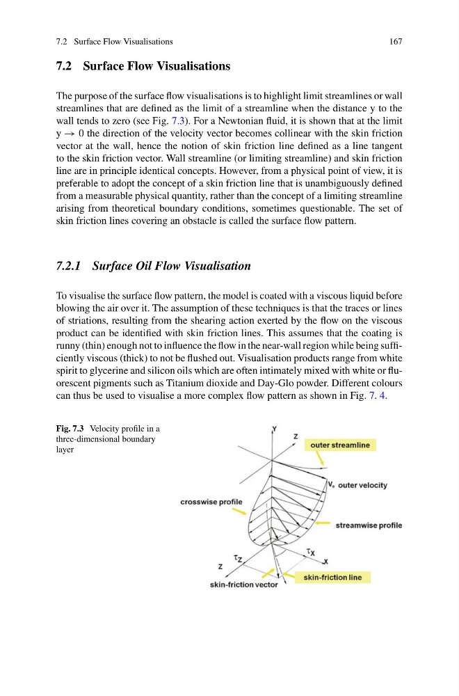
The purpose of the surface flow visualisations is to highlight limit streamlines or wall
streamlines that are defined as the limit of a streamline when the distance y to the
wall tends to zero (see Fig. 7.3). For a Newtonian fluid, it is shown that at the limit
y → 0 the direction of the velocity vector becomes collinear with the skin friction
vector at the wall, hence the notion of skin friction line defined as a line tangent
to the skin friction vector. Wall streamline (or limiting streamline) and skin friction
line are in principle identical concepts. However, from a physical point of view, it is
preferable to adopt the concept of a skin friction line that is unambiguously defined
from a measurable physical quantity, rather than the concept of a limiting streamline
arising from theoretical boundary conditions, sometimes questionable. The set of
skin friction lines covering an obstacle is called the surface flow pattern.
7.2.1 Surface Oil Flow Visualisation
To visualise the surface flow pattern, the model is coated with a viscous liquid before
blowing the air over it. The assumption of these techniques is that the traces or lines
of striations, resulting from the shearing action exerted by the flow on the viscous
product can be identified with skin friction lines. This assumes that the coating is
runny (thin) enough not to influence the flow in the near-wall region while being sufficiently viscous (thick) to not be flushed out. Visualisation products range from white
spirit to glycerine and silicon oils which are often intimately mixed with white or fluorescent pigments such as Titanium dioxide and Day-Glo powder. Different colours
can thus be used to visualise a more complex flow pattern as shown in Fig. 7. 4.
Fig. 7.3 Velocity profile in a
three-dimensional boundary
layer
167
7.2 Surface Flow Visualisations
The purpose of the surface flow visualisations is to highlight limit streamlines or wall
streamlines that are defined as the limit of a streamline when the distance y to the
wall tends to zero (see Fig. 7.3). For a Newtonian fluid, it is shown that at the limit
y → 0 the direction of the velocity vector becomes collinear with the skin friction
vector at the wall, hence the notion of skin friction line defined as a line tangent
to the skin friction vector. Wall streamline (or limiting streamline) and skin friction
line are in principle identical concepts. However, from a physical point of view, it is
preferable to adopt the concept of a skin friction line that is unambiguously defined
from a measurable physical quantity, rather than the concept of a limiting streamline
arising from theoretical boundary conditions, sometimes questionable. The set of
skin friction lines covering an obstacle is called the surface flow pattern.
7.2.1 Surface Oil Flow Visualisation
To visualise the surface flow pattern, the model is coated with a viscous liquid before
blowing the air over it. The assumption of these techniques is that the traces or lines
of striations, resulting from the shearing action exerted by the flow on the viscous
product can be identified with skin friction lines. This assumes that the coating is
runny (thin) enough not to influence the flow in the near-wall region while being sufficiently viscous (thick) to not be flushed out. Visualisation products range from white
spirit to glycerine and silicon oils which are often intimately mixed with white or fluorescent pigments such as Titanium dioxide and Day-Glo powder. Different colours
can thus be used to visualise a more complex flow pattern as shown in Fig. 7. 4.
Fig. 7.3 Velocity profile in a
three-dimensional boundary
layer