

146
6 Hypersonic Wind Tunnels
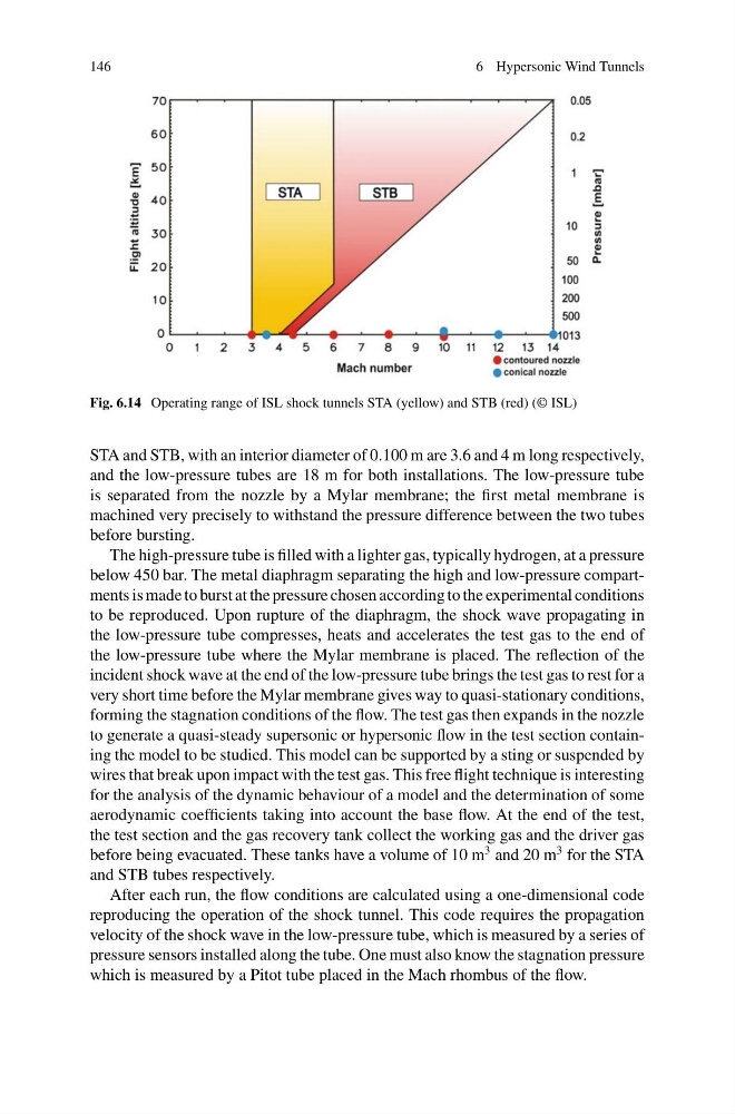
Fig. 6.14 Operating range of ISL shock tunnels STA (yellow) and STB (red) (© ISL)
STA and STB, with an interior diameter of 0.100 m are 3.6 and 4 m long respectively,
and the low-pressure tubes are 18 m for both installations. The low-pressure tube
is separated from the nozzle by a Mylar membrane; the first metal membrane is
machined very precisely to withstand the pressure difference between the two tubes
before bursting.
The high-pressure tube is filled with a lighter gas, typically hydrogen, at a pressure
below 450 bar. The metal diaphragm separating the high and low-pressure compartments is made to burst at the pressure chosen according to the experimental conditions
to be reproduced. Upon rupture of the diaphragm, the shock wave propagating in
the low-pressure tube compresses, heats and accelerates the test gas to the end of
the low-pressure tube where the Mylar membrane is placed. The reflection of the
incident shock wave at the end of the low-pressure tube brings the test gas to rest for a
very short time before the Mylar membrane gives way to quasi-stationary conditions,
forming the stagnation conditions of the flow. The test gas then expands in the nozzle
to generate a quasi-steady supersonic or hypersonic flow in the test section containing the model to be studied. This model can be supported by a sting or suspended by
wires that break upon impact with the test gas. This free flight technique is interesting
for the analysis of the dynamic behaviour of a model and the determination of some
aerodynamic coefficients taking into account the base flow. At the end of the test,
the test section and the gas recovery tank collect the working gas and the driver gas
before being evacuated. These tanks have a volume of 10 m
3 and 20 m
3 for the STA
and STB tubes respectively.
After each run, the flow conditions are calculated using a one-dimensional code
reproducing the operation of the shock tunnel. This code requires the propagation
velocity of the shock wave in the low-pressure tube, which is measured by a series of
pressure sensors installed along the tube. One must also know the stagnation pressure
which is measured by a Pitot tube placed in the Mach rhombus of the flow.
6 Hypersonic Wind Tunnels
Fig. 6.14 Operating range of ISL shock tunnels STA (yellow) and STB (red) (© ISL)
STA and STB, with an interior diameter of 0.100 m are 3.6 and 4 m long respectively,
and the low-pressure tubes are 18 m for both installations. The low-pressure tube
is separated from the nozzle by a Mylar membrane; the first metal membrane is
machined very precisely to withstand the pressure difference between the two tubes
before bursting.
The high-pressure tube is filled with a lighter gas, typically hydrogen, at a pressure
below 450 bar. The metal diaphragm separating the high and low-pressure compartments is made to burst at the pressure chosen according to the experimental conditions
to be reproduced. Upon rupture of the diaphragm, the shock wave propagating in
the low-pressure tube compresses, heats and accelerates the test gas to the end of
the low-pressure tube where the Mylar membrane is placed. The reflection of the
incident shock wave at the end of the low-pressure tube brings the test gas to rest for a
very short time before the Mylar membrane gives way to quasi-stationary conditions,
forming the stagnation conditions of the flow. The test gas then expands in the nozzle
to generate a quasi-steady supersonic or hypersonic flow in the test section containing the model to be studied. This model can be supported by a sting or suspended by
wires that break upon impact with the test gas. This free flight technique is interesting
for the analysis of the dynamic behaviour of a model and the determination of some
aerodynamic coefficients taking into account the base flow. At the end of the test,
the test section and the gas recovery tank collect the working gas and the driver gas
before being evacuated. These tanks have a volume of 10 m
3 and 20 m
3 for the STA
and STB tubes respectively.
After each run, the flow conditions are calculated using a one-dimensional code
reproducing the operation of the shock tunnel. This code requires the propagation
velocity of the shock wave in the low-pressure tube, which is measured by a series of
pressure sensors installed along the tube. One must also know the stagnation pressure
which is measured by a Pitot tube placed in the Mach rhombus of the flow.