

144
6 Hypersonic Wind Tunnels
– a shock wave in the working gas, propagating towards the right-hand side which
passes from state 1 to state 2 characterised by a temperature which can be very
high;
– a centred expansion wave in the driver gas, propagating towards the left-hand side
forces the flow passing from state (4) to state (3); the fluids in states (2) and (3)
are separated by the contact surface, also called interface.
The intensity of the shock produced is higher as the pressure p 4 is higher compared
to p 1 and the density of the driver gas is lower, which favours the use of helium or
hydrogen, which can be heated also. The shock tube is a simple means of obtaining
a flow at high pressure and temperature which may exceed 8000 K, for tubes using
hydrogen as driver gas.
In shock tubes, or shock tunnels, the working gas is used to feed a nozzle with a
large expansion ratio so as to achieve both a hypersonic (high Mach number) and a
hyper enthalpic (high total enthalpy) flow. After the passage of the shock, the nozzle
placed at the end of the tube is fed for a very short time (a few milliseconds) by the
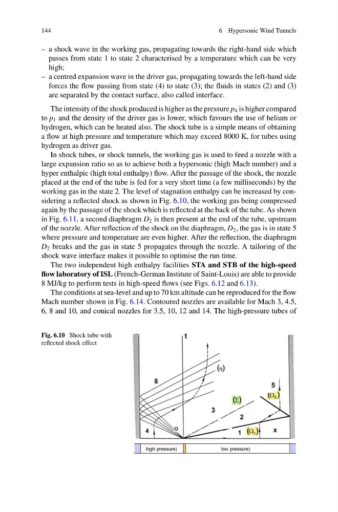
working gas in the state 2. The level of stagnation enthalpy can be increased by considering a reflected shock as shown in Fig. 6.10, the working gas being compressed
again by the passage of the shock which is reflected at the back of the tube. As shown
in Fig. 6.11, a second diaphragm D 2 is then present at the end of the tube, upstream
of the nozzle. After reflection of the shock on the diaphragm, D 2 , the gas is in state 5
where pressure and temperature are even higher. After the reflection, the diaphragm
D 2 breaks and the gas in state 5 propagates through the nozzle. A tailoring of the
shock wave interface makes it possible to optimise the run time.
The two independent high enthalpy facilities STA and STB of the high-speed
flow laboratory of ISL (French-German Institute of Saint-Louis) are able to provide
8 MJ/kg to perform tests in high-speed flows (see Figs. 6.12 and 6.13).
The conditions at sea-level and up to 70 km altitude can be reproduced for the flow
Mach number shown in Fig. 6.14. Contoured nozzles are available for Mach 3, 4.5,
6, 8 and 10, and conical nozzles for 3.5, 10, 12 and 14. The high-pressure tubes of
Fig. 6.10 Shock tube with
reflected shock effect
6 Hypersonic Wind Tunnels
– a shock wave in the working gas, propagating towards the right-hand side which
passes from state 1 to state 2 characterised by a temperature which can be very
high;
– a centred expansion wave in the driver gas, propagating towards the left-hand side
forces the flow passing from state (4) to state (3); the fluids in states (2) and (3)
are separated by the contact surface, also called interface.
The intensity of the shock produced is higher as the pressure p 4 is higher compared
to p 1 and the density of the driver gas is lower, which favours the use of helium or
hydrogen, which can be heated also. The shock tube is a simple means of obtaining
a flow at high pressure and temperature which may exceed 8000 K, for tubes using
hydrogen as driver gas.
In shock tubes, or shock tunnels, the working gas is used to feed a nozzle with a
large expansion ratio so as to achieve both a hypersonic (high Mach number) and a
hyper enthalpic (high total enthalpy) flow. After the passage of the shock, the nozzle
placed at the end of the tube is fed for a very short time (a few milliseconds) by the
working gas in the state 2. The level of stagnation enthalpy can be increased by considering a reflected shock as shown in Fig. 6.10, the working gas being compressed
again by the passage of the shock which is reflected at the back of the tube. As shown
in Fig. 6.11, a second diaphragm D 2 is then present at the end of the tube, upstream
of the nozzle. After reflection of the shock on the diaphragm, D 2 , the gas is in state 5
where pressure and temperature are even higher. After the reflection, the diaphragm
D 2 breaks and the gas in state 5 propagates through the nozzle. A tailoring of the
shock wave interface makes it possible to optimise the run time.
The two independent high enthalpy facilities STA and STB of the high-speed
flow laboratory of ISL (French-German Institute of Saint-Louis) are able to provide
8 MJ/kg to perform tests in high-speed flows (see Figs. 6.12 and 6.13).
The conditions at sea-level and up to 70 km altitude can be reproduced for the flow
Mach number shown in Fig. 6.14. Contoured nozzles are available for Mach 3, 4.5,
6, 8 and 10, and conical nozzles for 3.5, 10, 12 and 14. The high-pressure tubes of
Fig. 6.10 Shock tube with
reflected shock effect