

98
4 Transonic Wind Tunnels
4.2 Blockage Reduction and Flow Un-Chocking
4.2.1 Perforated or Slotted Walls
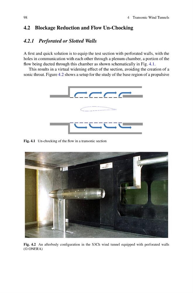
A first and quick solution is to equip the test section with perforated walls, with the
holes in communication with each other through a plenum chamber, a portion of the
flow being ducted through this chamber as shown schematically in Fig. 4.1.
This results in a virtual widening effect of the section, avoiding the creation of a
sonic throat. Figure 4.2 shows a setup for the study of the base region of a propulsive
Fig. 4.1 Un-chocking of the flow in a transonic section
Fig. 4.2 An afterbody configuration in the S3Ch wind tunnel equipped with perforated walls
(© ONERA)
4 Transonic Wind Tunnels
4.2 Blockage Reduction and Flow Un-Chocking
4.2.1 Perforated or Slotted Walls
A first and quick solution is to equip the test section with perforated walls, with the
holes in communication with each other through a plenum chamber, a portion of the
flow being ducted through this chamber as shown schematically in Fig. 4.1.
This results in a virtual widening effect of the section, avoiding the creation of a
sonic throat. Figure 4.2 shows a setup for the study of the base region of a propulsive
Fig. 4.1 Un-chocking of the flow in a transonic section
Fig. 4.2 An afterbody configuration in the S3Ch wind tunnel equipped with perforated walls
(© ONERA)