

3.2 Special Purpose Wind Tunnels
77
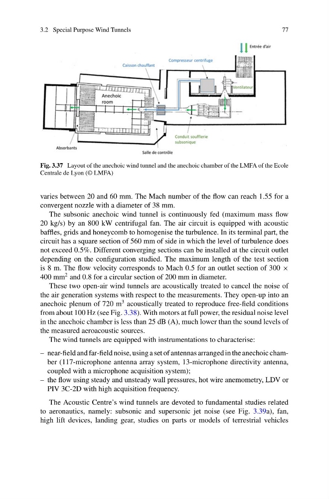
Fig. 3.37 Layout of the anechoic wind tunnel and the anechoic chamber of the LMFA of the Ecole
Centrale de Lyon (© LMFA)
varies between 20 and 60 mm. The Mach number of the flow can reach 1.55 for a
convergent nozzle with a diameter of 38 mm.
The subsonic anechoic wind tunnel is continuously fed (maximum mass flow
20 kg/s) by an 800 kW centrifugal fan. The air circuit is equipped with acoustic
baffles, grids and honeycomb to homogenise the turbulence. In its terminal part, the
circuit has a square section of 560 mm of side in which the level of turbulence does
not exceed 0.5%. Different converging sections can be installed at the circuit outlet
depending on the configuration studied. The maximum length of the test section
is 8 m. The flow velocity corresponds to Mach 0.5 for an outlet section of 300 ×
400 mm
2 and 0.8 for a circular section of 200 mm in diameter.
These two open-air wind tunnels are acoustically treated to cancel the noise of
the air generation systems with respect to the measurements. They open-up into an
anechoic plenum of 720 m
3 acoustically treated to reproduce free-field conditions
from about 100 Hz (see Fig. 3.38). With motors at full power, the residual noise level
in the anechoic chamber is less than 25 dB (A), much lower than the sound levels of
the measured aeroacoustic sources.
The wind tunnels are equipped with instrumentations to characterise:
– near-field and far-field noise, using a set of antennas arranged in the anechoic chamber (117-microphone antenna array system, 13-microphone directivity antenna,
coupled with a microphone acquisition system);
– the flow using steady and unsteady wall pressures, hot wire anemometry, LDV or
PIV 3C-2D with high acquisition frequency.
The Acoustic Centre’s wind tunnels are devoted to fundamental studies related
to aeronautics, namely: subsonic and supersonic jet noise (see Fig. 3.39a), fan,
high lift devices, landing gear, studies on parts or models of terrestrial vehicles
77
Fig. 3.37 Layout of the anechoic wind tunnel and the anechoic chamber of the LMFA of the Ecole
Centrale de Lyon (© LMFA)
varies between 20 and 60 mm. The Mach number of the flow can reach 1.55 for a
convergent nozzle with a diameter of 38 mm.
The subsonic anechoic wind tunnel is continuously fed (maximum mass flow
20 kg/s) by an 800 kW centrifugal fan. The air circuit is equipped with acoustic
baffles, grids and honeycomb to homogenise the turbulence. In its terminal part, the
circuit has a square section of 560 mm of side in which the level of turbulence does
not exceed 0.5%. Different converging sections can be installed at the circuit outlet
depending on the configuration studied. The maximum length of the test section
is 8 m. The flow velocity corresponds to Mach 0.5 for an outlet section of 300 ×
400 mm
2 and 0.8 for a circular section of 200 mm in diameter.
These two open-air wind tunnels are acoustically treated to cancel the noise of
the air generation systems with respect to the measurements. They open-up into an
anechoic plenum of 720 m
3 acoustically treated to reproduce free-field conditions
from about 100 Hz (see Fig. 3.38). With motors at full power, the residual noise level
in the anechoic chamber is less than 25 dB (A), much lower than the sound levels of
the measured aeroacoustic sources.
The wind tunnels are equipped with instrumentations to characterise:
– near-field and far-field noise, using a set of antennas arranged in the anechoic chamber (117-microphone antenna array system, 13-microphone directivity antenna,
coupled with a microphone acquisition system);
– the flow using steady and unsteady wall pressures, hot wire anemometry, LDV or
PIV 3C-2D with high acquisition frequency.
The Acoustic Centre’s wind tunnels are devoted to fundamental studies related
to aeronautics, namely: subsonic and supersonic jet noise (see Fig. 3.39a), fan,
high lift devices, landing gear, studies on parts or models of terrestrial vehicles