

140
M. Kanasaki et al.
7.2.4 Proof-of-Principal Experiments of Range
Determination Using CR-39
α-particles with energies of 1.68, 2.77, 3.83, 4.77 MeV from an
241 Am source irradiated CR-39 detectors (BARYOTRAK, Fukuvi Chemical Industry). The energies
were controlled by the distance in air using a variable-thickness collimator. The irradiated sample was chemically etched in a stirred 6 M KOH solution kept at 70
◦ C. To
obtain the growth curves of the etch pits at each energy, chemical etching and microscope observations were repeated every 30 min, which is referred to as a multi-step
etching technique.
Note that the radii of the etch pits were measured by reflected-light optical
microscopy. The accuracy of the measurements, which depends on the resolution
of the optical microscope, is approximately 0.1 µm. On the other hand, the thickness
of layer removed usually includes an error of ±0.5 µm when using a conventional
micrometre. In addition, the thickness of CR-39 detectors after chemical etching is
difficult to measure by a micrometre. This is because CR-39 detectors swell by water
absorption during chemical etching. To reduce such errors, we considered the average radius of the etch pits by fission fragments from a
252 Cf source as the thickness of
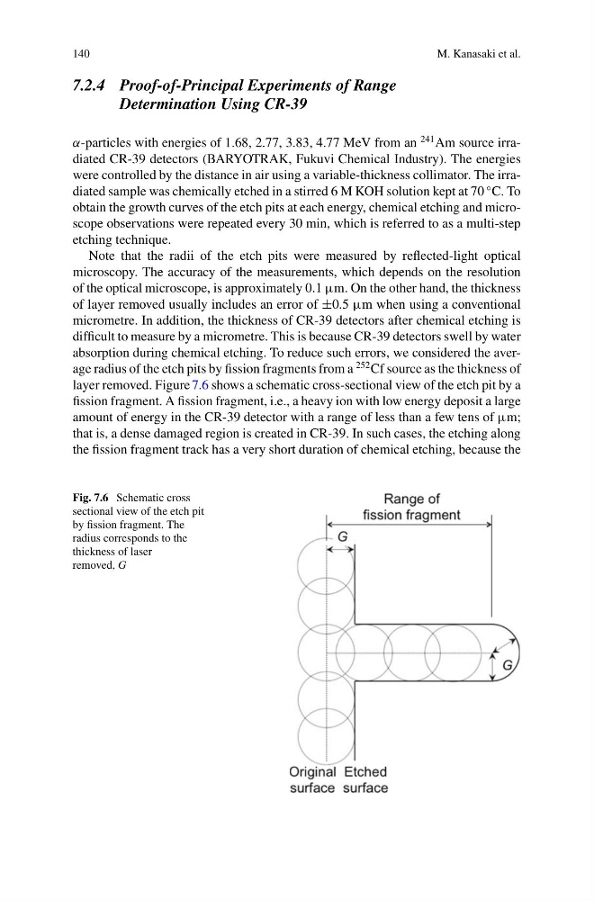
layer removed. Figure 7.6 shows a schematic cross-sectional view of the etch pit by a
fission fragment. A fission fragment, i.e., a heavy ion with low energy deposit a large
amount of energy in the CR-39 detector with a range of less than a few tens of µm;
that is, a dense damaged region is created in CR-39. In such cases, the etching along
the fission fragment track has a very short duration of chemical etching, because the
Fig. 7.6 Schematic cross
sectional view of the etch pit
by fission fragment. The
radius corresponds to the
thickness of laser
removed, G
M. Kanasaki et al.
7.2.4 Proof-of-Principal Experiments of Range
Determination Using CR-39
α-particles with energies of 1.68, 2.77, 3.83, 4.77 MeV from an
241 Am source irradiated CR-39 detectors (BARYOTRAK, Fukuvi Chemical Industry). The energies
were controlled by the distance in air using a variable-thickness collimator. The irradiated sample was chemically etched in a stirred 6 M KOH solution kept at 70
◦ C. To
obtain the growth curves of the etch pits at each energy, chemical etching and microscope observations were repeated every 30 min, which is referred to as a multi-step
etching technique.
Note that the radii of the etch pits were measured by reflected-light optical
microscopy. The accuracy of the measurements, which depends on the resolution
of the optical microscope, is approximately 0.1 µm. On the other hand, the thickness
of layer removed usually includes an error of ±0.5 µm when using a conventional
micrometre. In addition, the thickness of CR-39 detectors after chemical etching is
difficult to measure by a micrometre. This is because CR-39 detectors swell by water
absorption during chemical etching. To reduce such errors, we considered the average radius of the etch pits by fission fragments from a
252 Cf source as the thickness of
layer removed. Figure 7.6 shows a schematic cross-sectional view of the etch pit by a
fission fragment. A fission fragment, i.e., a heavy ion with low energy deposit a large
amount of energy in the CR-39 detector with a range of less than a few tens of µm;
that is, a dense damaged region is created in CR-39. In such cases, the etching along
the fission fragment track has a very short duration of chemical etching, because the
Fig. 7.6 Schematic cross
sectional view of the etch pit
by fission fragment. The
radius corresponds to the
thickness of laser
removed, G