

7.2 A Trojan-Resistant System …
665
Safe bus structure sometimes used a special counter to identify malicious effects
of Trojans similarly to a standard counter described above. When the expectation
time exceeds a certain threshold, the corresponding signal is generated to reset the
malicious waiting signal, which is also used as a latch enable signal for the master
device masking in order to identify the current master device as malicious.
7.2.5 Description of Operation of a System on Chip
Immediately After Detection of a Hardware Trojan
The method described above [29] allows detecting the presence of an embedded hardware Trojan with a high degree of probability as well as temporarily or constantly
ensure the special mode when the master or slave device will be identified as malicious. In the common case when the operation for exclusion of a malicious master
device or an entire slave device will leave such one-chip system in the state of
complete inability to operate in the set mode, the attack of the Trojan aimed at stopping the system will be successful. Therefore, it is extremely important not only
to guarantee detection of such devices, but also to maximize the ability of SoC to
effectively continue operation regardless of the identified presence of the Trojan. In
this case, corresponding countermeasures shall be based exclusively on the specific
nature of the Trojan.
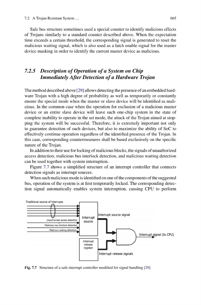
In addition to their use for locking of malicious blocks, the signals of unauthorized
access detection, malicious bus interlock detection, and malicious waiting detection
can be used together with system interruption.
Figure 7.7 shows a simplified structure of an interrupt controller that connects
detection signals as interrupt sources.
When such malicious mode is identified on one of the components of the suggested
bus, operation of the system is at first temporarily locked. The corresponding detection signal automatically enables system interruption, causing CPU to perform
Traditional source of interrupts
Unauthorized access detection
Malicious bus interlock detection
Malicious waiting detection
Interrupt
source
Interrupt source signal
Interrupt signal (to CPU)
Interrupt
release
register
Interrupt release signals
Fig. 7.7 Structure of a safe interrupt controller modified for signal handling [29]