

662
7 Countermeasures Against Hardware Trojans
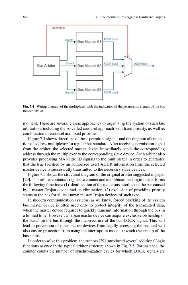
Fig. 7.4 Wiring diagram of the multiplexer with the indication of the permission signals of the bus
master device
moment. There are several classic approaches to organizing the system of such bus
arbitration, including the so-called carousel approach with fixed priority, as well as
combination of carousel and fixed priorities.
Figure 7.4 shows directions of these permitted signals and the diagram of connection of address multiplexor for regular bus standard. After receiving permission signal
from the arbiter, the selected master device immediately sends the corresponding
address through the multiplexer to the corresponding slave device. Such arbiter also
provides processing MASTER ID signals to the multiplexer in order to guarantee
that the true (verified by an authorized user) ADDR information from the selected
master device is successfully transmitted to the necessary slave devices.
Figure 7.5 shows the structural diagram of the original arbiter suggested in paper
[29]. This arbiter contains a register, a counter and a combinational logic and performs
the following functions: (1) identification of the malicious interlock of the bus caused
by a master Trojan device and its elimination; (2) exclusion of providing priority
status to the bus for all its known master Trojan devices of such type.
In modern communication systems, as we know, forced blocking of the system
bus master device is often used only to protect integrity of the transmitted data,
when the master device requires to quickly transmit information through the bus in
a limited time. However, a Trojan master device can acquire exclusive ownership of
the status on the bus through the incorrect use of the bus LOCK signal. This will
lead to prevention of other master devices from legally accessing the bus and will
also ensure protection from using the interruption mode to switch ownership of the
bus status.
In order to solve this problem, the authors [29] introduced several additional logic
functions at once in the typical arbiter structure shown in Fig. 7.5. For instance, the
counter counts the number of synchronization cycles for which LOCK signals are