

588
6 Reverse Engineering of Microcircuits
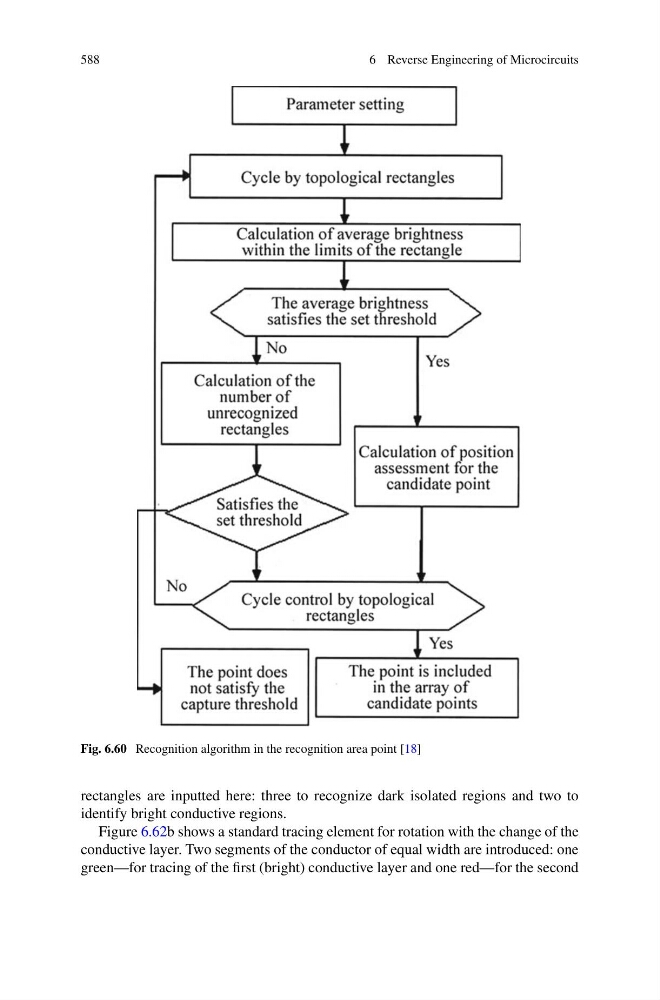
Fig. 6.60 Recognition algorithm in the recognition area point [18]
rectangles are inputted here: three to recognize dark isolated regions and two to
identify bright conductive regions.
Figure 6.62b shows a standard tracing element for rotation with the change of the
conductive layer. Two segments of the conductor of equal width are introduced: one
green—for tracing of the first (bright) conductive layer and one red—for the second
6 Reverse Engineering of Microcircuits
Fig. 6.60 Recognition algorithm in the recognition area point [18]
rectangles are inputted here: three to recognize dark isolated regions and two to
identify bright conductive regions.
Figure 6.62b shows a standard tracing element for rotation with the change of the
conductive layer. Two segments of the conductor of equal width are introduced: one
green—for tracing of the first (bright) conductive layer and one red—for the second