

6.5 Methods for Restoring Electrical Circuit …
587
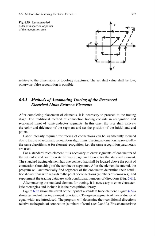
Fig. 6.59 Recommended
order of inspection of points
of the recognition area
relative to the dimensions of topology structures. The set shift value shall be low;
otherwise, false recognition is possible.
6.5.3 Methods of Automating Tracing of the Recovered
Electrical Links Between Elements
After completing placement of elements, it is necessary to proceed to the tracing
stage. The traditional method of connection tracing consists in recognition and
sequential input of semiconductor segments. In this case, the user shall indicate
the color and thickness of the segment and set the position of the initial and end
points.
Labor intensity required for tracing of connections can be significantly reduced
due to the use of automatic recognition algorithms. Tracing automation is provided by
the same algorithms as for element recognition, i.e., the same recognition parameters
are used.
For a standard trace element, it is necessary to enter segments of conductors of
the set color and width on its bitmap image and then enter the standard element.
The standard tracing element has one contact that shall be located above the point of
connection (branching) of the conductor segments. After the element is entered, the
program will automatically find segments of the conductor, determine their conditional directions with regards to the point of connections (numbers of semi-axes), and
supplement the tracing database with conditional numbers of directions (Fig. 6.61).
After entering the standard element for tracing, it is necessary to enter characteristic rectangles and include it in the recognition library.
Figure 6.62 shows the result of the input of a standard trace element. Figure 6.62a
shows a standard tracing element for rotation. Two green segments of the conductor of
equal width are introduced. The program will determine their conditional directions
relative to the point of connection (numbers of semi-axes 2 and 3). Five characteristic
587
Fig. 6.59 Recommended
order of inspection of points
of the recognition area
relative to the dimensions of topology structures. The set shift value shall be low;
otherwise, false recognition is possible.
6.5.3 Methods of Automating Tracing of the Recovered
Electrical Links Between Elements
After completing placement of elements, it is necessary to proceed to the tracing
stage. The traditional method of connection tracing consists in recognition and
sequential input of semiconductor segments. In this case, the user shall indicate
the color and thickness of the segment and set the position of the initial and end
points.
Labor intensity required for tracing of connections can be significantly reduced
due to the use of automatic recognition algorithms. Tracing automation is provided by
the same algorithms as for element recognition, i.e., the same recognition parameters
are used.
For a standard trace element, it is necessary to enter segments of conductors of
the set color and width on its bitmap image and then enter the standard element.
The standard tracing element has one contact that shall be located above the point of
connection (branching) of the conductor segments. After the element is entered, the
program will automatically find segments of the conductor, determine their conditional directions with regards to the point of connections (numbers of semi-axes), and
supplement the tracing database with conditional numbers of directions (Fig. 6.61).
After entering the standard element for tracing, it is necessary to enter characteristic rectangles and include it in the recognition library.
Figure 6.62 shows the result of the input of a standard trace element. Figure 6.62a
shows a standard tracing element for rotation. Two green segments of the conductor of
equal width are introduced. The program will determine their conditional directions
relative to the point of connection (numbers of semi-axes 2 and 3). Five characteristic