

6.4 Complex Methodology for Reverse Engineering …
563
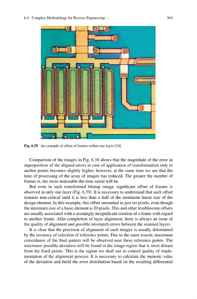
Fig. 6.39 An example of offset of frames within one layer [10]
Comparison of the images in Fig. 6.38 shows that the magnitude of the error in
superposition of the aligned errors in case of application of transformation only to
anchor points becomes slightly higher; however, at the same time we see that the
time of processing of the array of images has reduced. The greater the number of
frames is, the more noticeable the time saved will be.
But even in such transformed bitmap image, significant offset of frames is
observed in only one layer (Fig. 6.39). It is necessary to understand that such offset
remains non-critical until it is less than a half of the minimum linear size of the
design element. In this example, this offset amounted to just six pixels, even though
the minimum size of a basic element is 20 pixels. This and other troublesome offsets
are usually associated with a seemingly insignificant rotation of a frame with regard
to another frame. After completion of layer alignment, there is always an issue of
the quality of alignment and possible mismatch errors between the scanned layers.
It is clear that the precision of alignment of such images is usually determined
by the accuracy of selection of reference points. Due to the same reason, maximum
coincidence of the final pattern will be observed near these reference points. The
maximum possible deviation will be found in the image region that is most distant
from the fixed points. This is the region we shall use to control quality of implementation of the alignment process. It is necessary to calculate the numeric value
of the deviation and build the error distribution based on the resulting differential
563
Fig. 6.39 An example of offset of frames within one layer [10]
Comparison of the images in Fig. 6.38 shows that the magnitude of the error in
superposition of the aligned errors in case of application of transformation only to
anchor points becomes slightly higher; however, at the same time we see that the
time of processing of the array of images has reduced. The greater the number of
frames is, the more noticeable the time saved will be.
But even in such transformed bitmap image, significant offset of frames is
observed in only one layer (Fig. 6.39). It is necessary to understand that such offset
remains non-critical until it is less than a half of the minimum linear size of the
design element. In this example, this offset amounted to just six pixels, even though
the minimum size of a basic element is 20 pixels. This and other troublesome offsets
are usually associated with a seemingly insignificant rotation of a frame with regard
to another frame. After completion of layer alignment, there is always an issue of
the quality of alignment and possible mismatch errors between the scanned layers.
It is clear that the precision of alignment of such images is usually determined
by the accuracy of selection of reference points. Due to the same reason, maximum
coincidence of the final pattern will be observed near these reference points. The
maximum possible deviation will be found in the image region that is most distant
from the fixed points. This is the region we shall use to control quality of implementation of the alignment process. It is necessary to calculate the numeric value
of the deviation and build the error distribution based on the resulting differential