

6.4 Complex Methodology for Reverse Engineering …
561
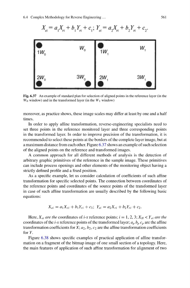
Fig. 6.37 An example of standard plan for selection of aligned points in the reference layer (in the
W 0 window) and in the transformed layer (in the W 1 window)
moreover, as practice shows, these image scales may differ at least by one and a half
times.
In order to apply affine transformation, reverse-engineering specialists need to
set three points in the reference monitored layer and three corresponding points
in the transformed layer. In order to improve precision of the transformation, it is
recommended to select these points at the borders of the complete layer image, but at
a maximum distance from each other. Figure 6.37 shows an example of such selection
of the aligned points on the reference and transformed images.
A common approach for all different methods of analysis is the detection of
arbitrary graphic primitives of the reference in the sample image. These primitives
can include process openings and other elements of the monitoring object having a
strictly defined profile and a fixed position.
As a specific example, let us consider calculation of coefficients of such affine
transformation for specific selected points. The connection between coordinates of
the reference points and coordinates of the source points of the transformed layer
in case of such affine transformation are usually described by the following basic
equations:
X ei = a 1 X ri + b 1 Y ri + c 1 ; Y ei = a 2 X ri + b 2 Y ri + c 2 .
Here, X ei are the coordinates of i-x reference points; i = 1, 2, 3; X H < Y ei are the
coordinates of the i-x reference points of the transformed layer; a p b p c p are the affine
transformation coefficients for X; a 2 , b 2 , c 2 are the affine transformation coefficients
for Y.
Figure 6.38 shows specific examples of practical application of affine transformation on a fragment of the bitmap image of one small section of a topology. Here,
the main features of application of such affine transformation for alignment of two
561
Fig. 6.37 An example of standard plan for selection of aligned points in the reference layer (in the
W 0 window) and in the transformed layer (in the W 1 window)
moreover, as practice shows, these image scales may differ at least by one and a half
times.
In order to apply affine transformation, reverse-engineering specialists need to
set three points in the reference monitored layer and three corresponding points
in the transformed layer. In order to improve precision of the transformation, it is
recommended to select these points at the borders of the complete layer image, but at
a maximum distance from each other. Figure 6.37 shows an example of such selection
of the aligned points on the reference and transformed images.
A common approach for all different methods of analysis is the detection of
arbitrary graphic primitives of the reference in the sample image. These primitives
can include process openings and other elements of the monitoring object having a
strictly defined profile and a fixed position.
As a specific example, let us consider calculation of coefficients of such affine
transformation for specific selected points. The connection between coordinates of
the reference points and coordinates of the source points of the transformed layer
in case of such affine transformation are usually described by the following basic
equations:
X ei = a 1 X ri + b 1 Y ri + c 1 ; Y ei = a 2 X ri + b 2 Y ri + c 2 .
Here, X ei are the coordinates of i-x reference points; i = 1, 2, 3; X H < Y ei are the
coordinates of the i-x reference points of the transformed layer; a p b p c p are the affine
transformation coefficients for X; a 2 , b 2 , c 2 are the affine transformation coefficients
for Y.
Figure 6.38 shows specific examples of practical application of affine transformation on a fragment of the bitmap image of one small section of a topology. Here,
the main features of application of such affine transformation for alignment of two