

550
6 Reverse Engineering of Microcircuits
6.4.2 Specific Features of Implementing Frame-by-Frame
Alignment of Topology Fragments
Obtaining a digital photograph of an IC chip with linear dimensions of several
millimeters or more at large magnifications remains a rather labor-intensive task,
since it involves photographing several hundred overlapping fragments and their
subsequent integration into a single panorama. Fragment-by-fragment system is
usually used for acquisition of such images.
The main difference between fragment-by-fragment scanning systems and regular
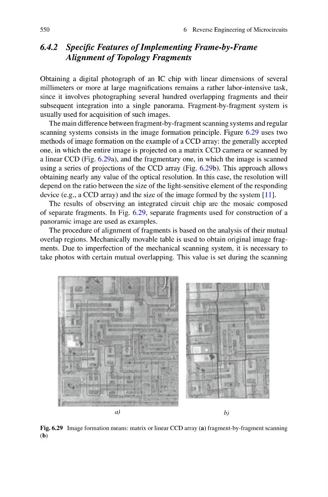
scanning systems consists in the image formation principle. Figure 6.29 uses two
methods of image formation on the example of a CCD array: the generally accepted
one, in which the entire image is projected on a matrix CCD camera or scanned by
a linear CCD (Fig. 6.29a), and the fragmentary one, in which the image is scanned
using a series of projections of the CCD array (Fig. 6.29b). This approach allows
obtaining nearly any value of the optical resolution. In this case, the resolution will
depend on the ratio between the size of the light-sensitive element of the responding
device (e.g., a CCD array) and the size of the image formed by the system [11].
The results of observing an integrated circuit chip are the mosaic composed
of separate fragments. In Fig. 6.29, separate fragments used for construction of a
panoramic image are used as examples.
The procedure of alignment of fragments is based on the analysis of their mutual
overlap regions. Mechanically movable table is used to obtain original image fragments. Due to imperfection of the mechanical scanning system, it is necessary to
take photos with certain mutual overlapping. This value is set during the scanning
a)
b)
Fig. 6.29 Image formation means: matrix or linear CCD array (a) fragment-by-fragment scanning
(b)
6 Reverse Engineering of Microcircuits
6.4.2 Specific Features of Implementing Frame-by-Frame
Alignment of Topology Fragments
Obtaining a digital photograph of an IC chip with linear dimensions of several
millimeters or more at large magnifications remains a rather labor-intensive task,
since it involves photographing several hundred overlapping fragments and their
subsequent integration into a single panorama. Fragment-by-fragment system is
usually used for acquisition of such images.
The main difference between fragment-by-fragment scanning systems and regular
scanning systems consists in the image formation principle. Figure 6.29 uses two
methods of image formation on the example of a CCD array: the generally accepted
one, in which the entire image is projected on a matrix CCD camera or scanned by
a linear CCD (Fig. 6.29a), and the fragmentary one, in which the image is scanned
using a series of projections of the CCD array (Fig. 6.29b). This approach allows
obtaining nearly any value of the optical resolution. In this case, the resolution will
depend on the ratio between the size of the light-sensitive element of the responding
device (e.g., a CCD array) and the size of the image formed by the system [11].
The results of observing an integrated circuit chip are the mosaic composed
of separate fragments. In Fig. 6.29, separate fragments used for construction of a
panoramic image are used as examples.
The procedure of alignment of fragments is based on the analysis of their mutual
overlap regions. Mechanically movable table is used to obtain original image fragments. Due to imperfection of the mechanical scanning system, it is necessary to
take photos with certain mutual overlapping. This value is set during the scanning
a)
b)
Fig. 6.29 Image formation means: matrix or linear CCD array (a) fragment-by-fragment scanning
(b)