

528
6 Reverse Engineering of Microcircuits
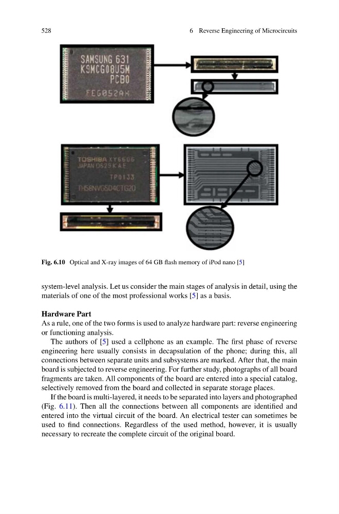
Fig. 6.10 Optical and X-ray images of 64 GB flash memory of iPod nano [5]
system-level analysis. Let us consider the main stages of analysis in detail, using the
materials of one of the most professional works [5] as a basis.
Hardware Part
As a rule, one of the two forms is used to analyze hardware part: reverse engineering
or functioning analysis.
The authors of [5] used a cellphone as an example. The first phase of reverse
engineering here usually consists in decapsulation of the phone; during this, all
connections between separate units and subsystems are marked. After that, the main
board is subjected to reverse engineering. For further study, photographs of all board
fragments are taken. All components of the board are entered into a special catalog,
selectively removed from the board and collected in separate storage places.
If the board is multi-layered, it needs to be separated into layers and photographed
(Fig. 6.11). Then all the connections between all components are identified and
entered into the virtual circuit of the board. An electrical tester can sometimes be
used to find connections. Regardless of the used method, however, it is usually
necessary to recreate the complete circuit of the original board.
6 Reverse Engineering of Microcircuits
Fig. 6.10 Optical and X-ray images of 64 GB flash memory of iPod nano [5]
system-level analysis. Let us consider the main stages of analysis in detail, using the
materials of one of the most professional works [5] as a basis.
Hardware Part
As a rule, one of the two forms is used to analyze hardware part: reverse engineering
or functioning analysis.
The authors of [5] used a cellphone as an example. The first phase of reverse
engineering here usually consists in decapsulation of the phone; during this, all
connections between separate units and subsystems are marked. After that, the main
board is subjected to reverse engineering. For further study, photographs of all board
fragments are taken. All components of the board are entered into a special catalog,
selectively removed from the board and collected in separate storage places.
If the board is multi-layered, it needs to be separated into layers and photographed
(Fig. 6.11). Then all the connections between all components are identified and
entered into the virtual circuit of the board. An electrical tester can sometimes be
used to find connections. Regardless of the used method, however, it is usually
necessary to recreate the complete circuit of the original board.