

4.7 Case Study of the Development …
367
effectiveness in reaching the final goal, we will detail the AM attack and only briefly
note its differences from the 50 MHz variation.
So, the data transmitted using the AM signal is more easily interpreted by humans.
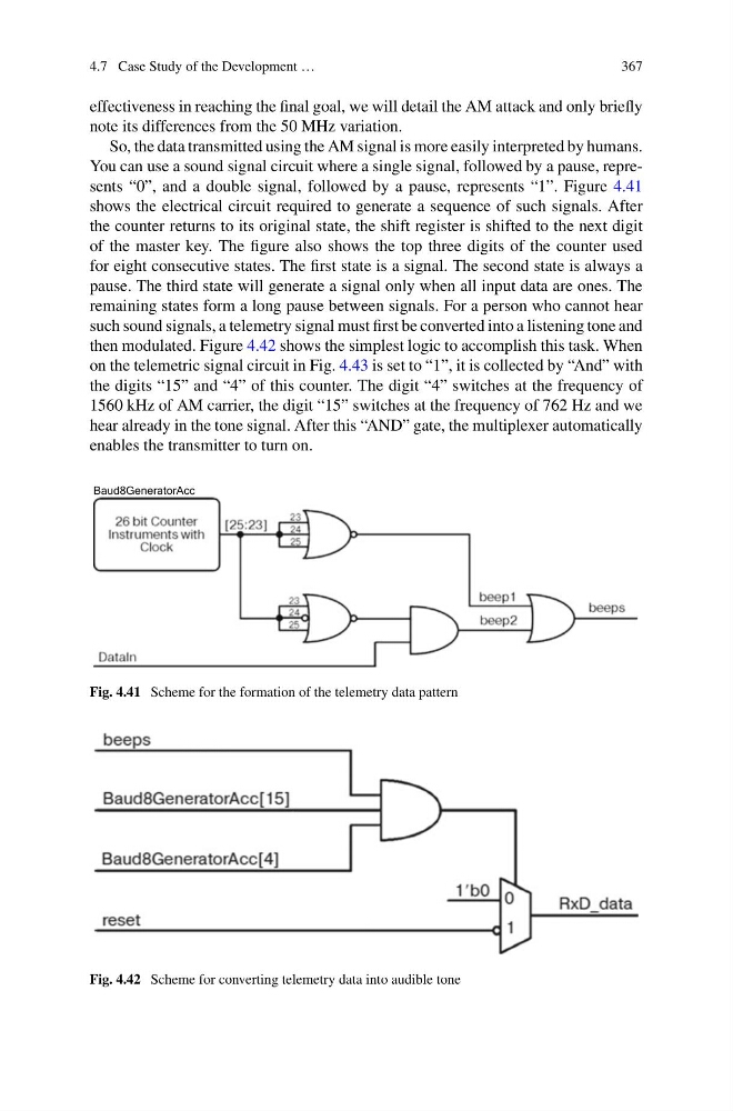
You can use a sound signal circuit where a single signal, followed by a pause, represents “0”, and a double signal, followed by a pause, represents “1”. Figure 4.41
shows the electrical circuit required to generate a sequence of such signals. After
the counter returns to its original state, the shift register is shifted to the next digit
of the master key. The figure also shows the top three digits of the counter used
for eight consecutive states. The first state is a signal. The second state is always a
pause. The third state will generate a signal only when all input data are ones. The
remaining states form a long pause between signals. For a person who cannot hear
such sound signals, a telemetry signal must first be converted into a listening tone and
then modulated. Figure 4.42 shows the simplest logic to accomplish this task. When
on the telemetric signal circuit in Fig. 4.43 is set to “1”, it is collected by “And” with
the digits “15” and “4” of this counter. The digit “4” switches at the frequency of
1560 kHz of AM carrier, the digit “15” switches at the frequency of 762 Hz and we
hear already in the tone signal. After this “AND” gate, the multiplexer automatically
enables the transmitter to turn on.
Baud8GeneratorAcc
Fig. 4.41 Scheme for the formation of the telemetry data pattern
Fig. 4.42 Scheme for converting telemetry data into audible tone
367
effectiveness in reaching the final goal, we will detail the AM attack and only briefly
note its differences from the 50 MHz variation.
So, the data transmitted using the AM signal is more easily interpreted by humans.
You can use a sound signal circuit where a single signal, followed by a pause, represents “0”, and a double signal, followed by a pause, represents “1”. Figure 4.41
shows the electrical circuit required to generate a sequence of such signals. After
the counter returns to its original state, the shift register is shifted to the next digit
of the master key. The figure also shows the top three digits of the counter used
for eight consecutive states. The first state is a signal. The second state is always a
pause. The third state will generate a signal only when all input data are ones. The
remaining states form a long pause between signals. For a person who cannot hear
such sound signals, a telemetry signal must first be converted into a listening tone and
then modulated. Figure 4.42 shows the simplest logic to accomplish this task. When
on the telemetric signal circuit in Fig. 4.43 is set to “1”, it is collected by “And” with
the digits “15” and “4” of this counter. The digit “4” switches at the frequency of
1560 kHz of AM carrier, the digit “15” switches at the frequency of 762 Hz and we
hear already in the tone signal. After this “AND” gate, the multiplexer automatically
enables the transmitter to turn on.
Baud8GeneratorAcc
Fig. 4.41 Scheme for the formation of the telemetry data pattern
Fig. 4.42 Scheme for converting telemetry data into audible tone