

36
G. K. Ananthasuresh
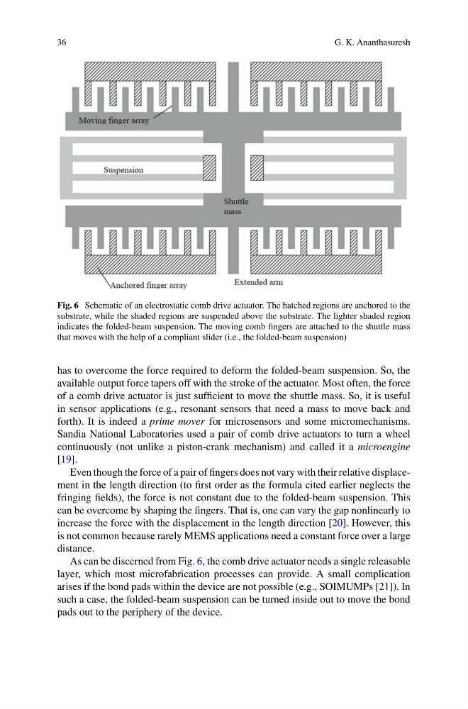
Fig. 6 Schematic of an electrostatic comb drive actuator. The hatched regions are anchored to the
substrate, while the shaded regions are suspended above the substrate. The lighter shaded region
indicates the folded-beam suspension. The moving comb fingers are attached to the shuttle mass
that moves with the help of a compliant slider (i.e., the folded-beam suspension)
has to overcome the force required to deform the folded-beam suspension. So, the
available output force tapers off with the stroke of the actuator. Most often, the force
of a comb drive actuator is just sufficient to move the shuttle mass. So, it is useful
in sensor applications (e.g., resonant sensors that need a mass to move back and
forth). It is indeed a prime mover for microsensors and some micromechanisms.
Sandia National Laboratories used a pair of comb drive actuators to turn a wheel
continuously (not unlike a piston-crank mechanism) and called it a microengine
[19].
Even though the force of a pair of fingers does not vary with their relative displacement in the length direction (to first order as the formula cited earlier neglects the
fringing fields), the force is not constant due to the folded-beam suspension. This
can be overcome by shaping the fingers. That is, one can vary the gap nonlinearly to
increase the force with the displacement in the length direction [20]. However, this
is not common because rarely MEMS applications need a constant force over a large
distance.
As can be discerned from Fig. 6, the comb drive actuator needs a single releasable
layer, which most microfabrication processes can provide. A small complication
arises if the bond pads within the device are not possible (e.g., SOIMUMPs [21]). In
such a case, the folded-beam suspension can be turned inside out to move the bond
pads out to the periphery of the device.
G. K. Ananthasuresh
Fig. 6 Schematic of an electrostatic comb drive actuator. The hatched regions are anchored to the
substrate, while the shaded regions are suspended above the substrate. The lighter shaded region
indicates the folded-beam suspension. The moving comb fingers are attached to the shuttle mass
that moves with the help of a compliant slider (i.e., the folded-beam suspension)
has to overcome the force required to deform the folded-beam suspension. So, the
available output force tapers off with the stroke of the actuator. Most often, the force
of a comb drive actuator is just sufficient to move the shuttle mass. So, it is useful
in sensor applications (e.g., resonant sensors that need a mass to move back and
forth). It is indeed a prime mover for microsensors and some micromechanisms.
Sandia National Laboratories used a pair of comb drive actuators to turn a wheel
continuously (not unlike a piston-crank mechanism) and called it a microengine
[19].
Even though the force of a pair of fingers does not vary with their relative displacement in the length direction (to first order as the formula cited earlier neglects the
fringing fields), the force is not constant due to the folded-beam suspension. This
can be overcome by shaping the fingers. That is, one can vary the gap nonlinearly to
increase the force with the displacement in the length direction [20]. However, this
is not common because rarely MEMS applications need a constant force over a large
distance.
As can be discerned from Fig. 6, the comb drive actuator needs a single releasable
layer, which most microfabrication processes can provide. A small complication
arises if the bond pads within the device are not possible (e.g., SOIMUMPs [21]). In
such a case, the folded-beam suspension can be turned inside out to move the bond
pads out to the periphery of the device.