

Simulations of Machining Processes at Small …
245
Here, h 0 and h s are the initial and saturated hardening moduli, respectively, q is
the latent hardening ratio, τ 0 and τ S are the shear stresses at the onset of yield and
the saturation of hardening, respectively, and γ is the accumulative shear strain over
all the slip systems.
3 Finite-Element Modelling Procedure
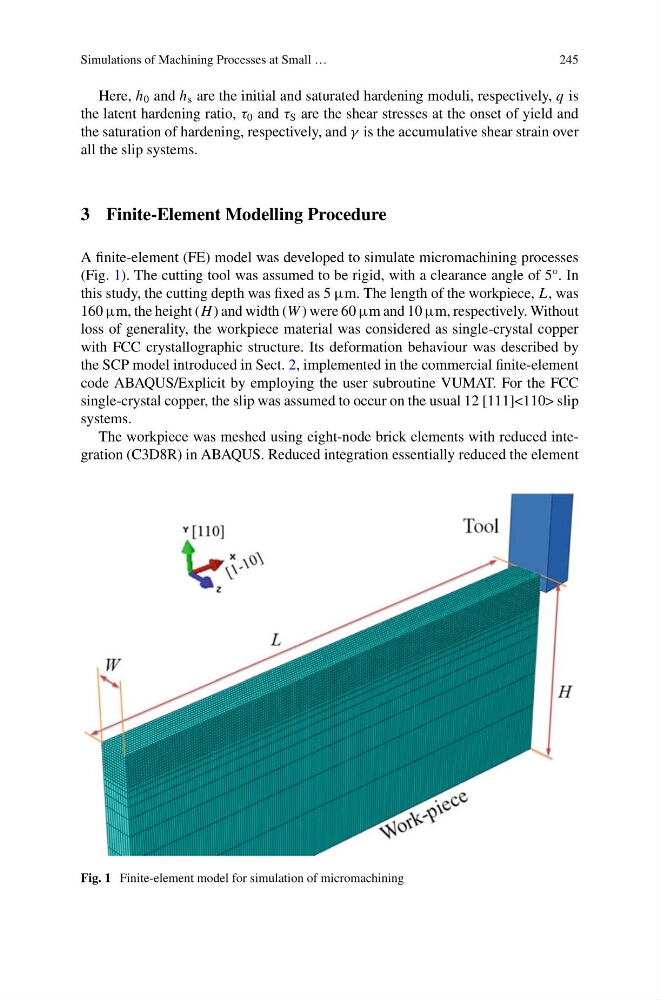
A finite-element (FE) model was developed to simulate micromachining processes
(Fig. 1). The cutting tool was assumed to be rigid, with a clearance angle of 5°. In
this study, the cutting depth was fixed as 5 μm. The length of the workpiece, L, was
160 μm, the height (H ) and width (W ) were 60 μm and 10 μm, respectively. Without
loss of generality, the workpiece material was considered as single-crystal copper
with FCC crystallographic structure. Its deformation behaviour was described by
the SCP model introduced in Sect. 2, implemented in the commercial finite-element
code ABAQUS/Explicit by employing the user subroutine VUMAT. For the FCC
single-crystal copper, the slip was assumed to occur on the usual 12 [111]<110> slip
systems.
The workpiece was meshed using eight-node brick elements with reduced integration (C3D8R) in ABAQUS. Reduced integration essentially reduced the element
Fig. 1 Finite-element model for simulation of micromachining
245
Here, h 0 and h s are the initial and saturated hardening moduli, respectively, q is
the latent hardening ratio, τ 0 and τ S are the shear stresses at the onset of yield and
the saturation of hardening, respectively, and γ is the accumulative shear strain over
all the slip systems.
3 Finite-Element Modelling Procedure
A finite-element (FE) model was developed to simulate micromachining processes
(Fig. 1). The cutting tool was assumed to be rigid, with a clearance angle of 5°. In
this study, the cutting depth was fixed as 5 μm. The length of the workpiece, L, was
160 μm, the height (H ) and width (W ) were 60 μm and 10 μm, respectively. Without
loss of generality, the workpiece material was considered as single-crystal copper
with FCC crystallographic structure. Its deformation behaviour was described by
the SCP model introduced in Sect. 2, implemented in the commercial finite-element
code ABAQUS/Explicit by employing the user subroutine VUMAT. For the FCC
single-crystal copper, the slip was assumed to occur on the usual 12 [111]<110> slip
systems.
The workpiece was meshed using eight-node brick elements with reduced integration (C3D8R) in ABAQUS. Reduced integration essentially reduced the element
Fig. 1 Finite-element model for simulation of micromachining