

Space Elevator—A Revolutionary Space Transportation System
111
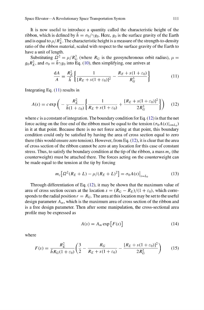
It is now useful to introduce a quantity called the characteristic height of the
ribbon, which is defined by ¯
h = σ 0 /γg 0 . Here, g 0 is the surface gravity of the Earth
and is equal to μ/R
2
E . The characteristic height is a measure of the strength-to-density
ratio of the ribbon material, scaled with respect to the surface gravity of the Earth to
have a unit of length.
Substituting Ω
2
= μ/R
3
G (where R G is the geosynchronous orbit radius), μ =
g 0 R
2
E , and σ 0 = ¯
hγg 0 into Eq. (10), then simplifying, one arrives at
dA
A
=
R
2
E
¯
h
1
[R E + s(1 + ε 0 )] 2 −
R E + s(1 + ε 0 )
R
3
G
(11)
Integrating Eq. (11) results in
A(s) = c exp
−
R
2
E
¯
h(1 + ε 0 )
1
R E + s(1 + ε 0 )
+
[R E + s(1 + ε 0 )]
2
2R
3
G
(12)
where c is a constant of integration. The boundary condition for Eq. (12) is that the net
force acting on the free end of the ribbon must be equal to the tension (σ 0 A(s)| s=L 0 )
in it at that point. Because there is no net force acting at that point, this boundary
condition could only be satisfied by having the area of cross section equal to zero
there (this would ensure zero tension). However, from Eq. (12), it is clear that the area
of cross section of the ribbon cannot be zero at any location for this case of constant
stress. Thus, to satisfy the boundary condition at the tip of the ribbon, a mass m c (the
counterweight) must be attached there. The forces acting on the counterweight can
be made equal to the tension at the tip by forcing
m c
Ω
2
(R E + L) − μ/(R E + L)
2
= σ 0 A(s)
s=L 0
(13)
Through differentiation of Eq. (12), it may be shown that the maximum value of
area of cross section occurs at the location s = (R G − R E )/(1 + ε 0 ), which corresponds to the radial position r = R G . The area at this location may be set to the useful
design parameter A m , which is the maximum area of cross section of the ribbon and
is a free design parameter. Then after some manipulation, the cross-sectional area
profile may be expressed as
A(s) = A m exp
F(s)
(14)
where
F(s) =
R
2
E
¯
h R G (1 + ε 0 )
3
2
−
R G
R E + s(1 + ε 0 )
−
[R E + s(1 + ε 0 )]
2
2R
2
G
(15)
111
It is now useful to introduce a quantity called the characteristic height of the
ribbon, which is defined by ¯
h = σ 0 /γg 0 . Here, g 0 is the surface gravity of the Earth
and is equal to μ/R
2
E . The characteristic height is a measure of the strength-to-density
ratio of the ribbon material, scaled with respect to the surface gravity of the Earth to
have a unit of length.
Substituting Ω
2
= μ/R
3
G (where R G is the geosynchronous orbit radius), μ =
g 0 R
2
E , and σ 0 = ¯
hγg 0 into Eq. (10), then simplifying, one arrives at
dA
A
=
R
2
E
¯
h
1
[R E + s(1 + ε 0 )] 2 −
R E + s(1 + ε 0 )
R
3
G
(11)
Integrating Eq. (11) results in
A(s) = c exp
−
R
2
E
¯
h(1 + ε 0 )
1
R E + s(1 + ε 0 )
+
[R E + s(1 + ε 0 )]
2
2R
3
G
(12)
where c is a constant of integration. The boundary condition for Eq. (12) is that the net
force acting on the free end of the ribbon must be equal to the tension (σ 0 A(s)| s=L 0 )
in it at that point. Because there is no net force acting at that point, this boundary
condition could only be satisfied by having the area of cross section equal to zero
there (this would ensure zero tension). However, from Eq. (12), it is clear that the area
of cross section of the ribbon cannot be zero at any location for this case of constant
stress. Thus, to satisfy the boundary condition at the tip of the ribbon, a mass m c (the
counterweight) must be attached there. The forces acting on the counterweight can
be made equal to the tension at the tip by forcing
m c
Ω
2
(R E + L) − μ/(R E + L)
2
= σ 0 A(s)
s=L 0
(13)
Through differentiation of Eq. (12), it may be shown that the maximum value of
area of cross section occurs at the location s = (R G − R E )/(1 + ε 0 ), which corresponds to the radial position r = R G . The area at this location may be set to the useful
design parameter A m , which is the maximum area of cross section of the ribbon and
is a free design parameter. Then after some manipulation, the cross-sectional area
profile may be expressed as
A(s) = A m exp
F(s)
(14)
where
F(s) =
R
2
E
¯
h R G (1 + ε 0 )
3
2
−
R G
R E + s(1 + ε 0 )
−
[R E + s(1 + ε 0 )]
2
2R
2
G
(15)