

Space Elevator—A Revolutionary Space Transportation System
107
Let us say that at the time of launch, the climber (and the satellite it contains)
will have a radial distance of r 0 (= d 0 + R E ), speed v 0 , and flight path angle β 0 . The
values of v 0 and β 0 may be modified by an applied velocity impulse, if desired. The
semi-major axis and eccentricity of the orbit that the satellite will fall into can be
written as [6]
a =
r 0
2 −
r 0 v
2
0
μ
(1)
and
e =
r 0 v
2
0
μ
− 1
2
cos 2 β 0 + sin
2
β 0
(2)
respectively, where μ = G M E is the gravitational constant of the Earth.
Ideally, at the moment of satellite launch, the space elevator will be static (other
than the nominal spin rate of the Earth), and in its nominal configuration consisting
of a vertical ribbon. If no additional impulse is applied to the satellite, then v 0 =
Ω(R E + d 0 ) and β 0 = 0, where R E and Ω are the radius and angular velocity of
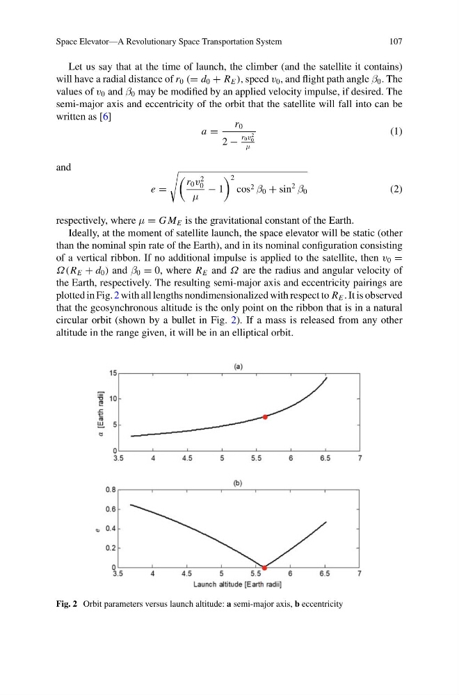
the Earth, respectively. The resulting semi-major axis and eccentricity pairings are
plotted in Fig. 2 with all lengths nondimensionalized with respect to R E . It is observed
that the geosynchronous altitude is the only point on the ribbon that is in a natural
circular orbit (shown by a bullet in Fig. 2). If a mass is released from any other
altitude in the range given, it will be in an elliptical orbit.
Fig. 2 Orbit parameters versus launch altitude: a semi-major axis, b eccentricity
107
Let us say that at the time of launch, the climber (and the satellite it contains)
will have a radial distance of r 0 (= d 0 + R E ), speed v 0 , and flight path angle β 0 . The
values of v 0 and β 0 may be modified by an applied velocity impulse, if desired. The
semi-major axis and eccentricity of the orbit that the satellite will fall into can be
written as [6]
a =
r 0
2 −
r 0 v
2
0
μ
(1)
and
e =
r 0 v
2
0
μ
− 1
2
cos 2 β 0 + sin
2
β 0
(2)
respectively, where μ = G M E is the gravitational constant of the Earth.
Ideally, at the moment of satellite launch, the space elevator will be static (other
than the nominal spin rate of the Earth), and in its nominal configuration consisting
of a vertical ribbon. If no additional impulse is applied to the satellite, then v 0 =
Ω(R E + d 0 ) and β 0 = 0, where R E and Ω are the radius and angular velocity of
the Earth, respectively. The resulting semi-major axis and eccentricity pairings are
plotted in Fig. 2 with all lengths nondimensionalized with respect to R E . It is observed
that the geosynchronous altitude is the only point on the ribbon that is in a natural
circular orbit (shown by a bullet in Fig. 2). If a mass is released from any other
altitude in the range given, it will be in an elliptical orbit.
Fig. 2 Orbit parameters versus launch altitude: a semi-major axis, b eccentricity