

96
C. Ozoegwu and P. Eberhard
0.5
1
1.5
2
2.5
spindle speed [rpm]
10
4
0
10
20
30
depth of cut [mm]
ref
p=1
p=2
p=3
p=4
p=5
p=6
p=7
p=8
p=9
p=10
(a)Unidirectional model
0.5
1
1.5
2
2.5
spindle speed [rpm]
10
4
0
10
20
30
depth of cut [mm]
(b)Bidirectional model
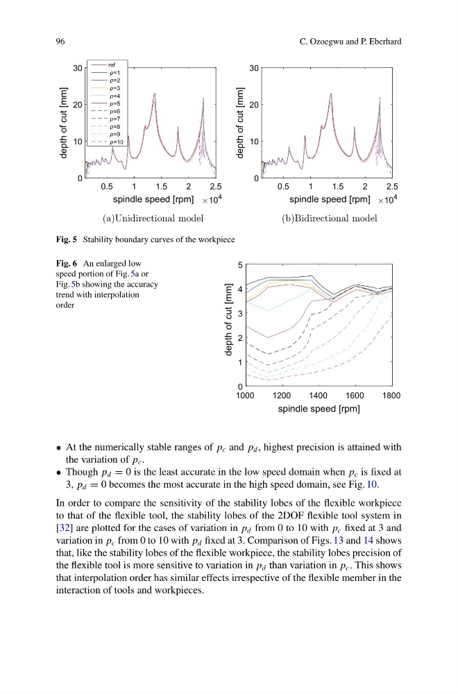
Fig. 5 Stability boundary curves of the workpiece
Fig. 6 An enlarged low
speed portion of Fig. 5a or
Fig. 5b showing the accuracy
trend with interpolation
order
1000
1200
1400
1600
1800
spindle speed [rpm]
0
1
2
3
4
5
depth of cut [mm]
• At the numerically stable ranges of p c and p d , highest precision is attained with
the variation of p c .
• Though p d = 0 is the least accurate in the low speed domain when p c is fixed at
3, p d = 0 becomes the most accurate in the high speed domain, see Fig. 10.
In order to compare the sensitivity of the stability lobes of the flexible workpiece
to that of the flexible tool, the stability lobes of the 2DOF flexible tool system in
[32] are plotted for the cases of variation in p d from 0 to 10 with p c fixed at 3 and
variation in p c from 0 to 10 with p d fixed at 3. Comparison of Figs. 13 and 14 shows
that, like the stability lobes of the flexible workpiece, the stability lobes precision of
the flexible tool is more sensitive to variation in p d than variation in p c . This shows
that interpolation order has similar effects irrespective of the flexible member in the
interaction of tools and workpieces.
C. Ozoegwu and P. Eberhard
0.5
1
1.5
2
2.5
spindle speed [rpm]
10
4
0
10
20
30
depth of cut [mm]
ref
p=1
p=2
p=3
p=4
p=5
p=6
p=7
p=8
p=9
p=10
(a)Unidirectional model
0.5
1
1.5
2
2.5
spindle speed [rpm]
10
4
0
10
20
30
depth of cut [mm]
(b)Bidirectional model
Fig. 5 Stability boundary curves of the workpiece
Fig. 6 An enlarged low
speed portion of Fig. 5a or
Fig. 5b showing the accuracy
trend with interpolation
order
1000
1200
1400
1600
1800
spindle speed [rpm]
0
1
2
3
4
5
depth of cut [mm]
• At the numerically stable ranges of p c and p d , highest precision is attained with
the variation of p c .
• Though p d = 0 is the least accurate in the low speed domain when p c is fixed at
3, p d = 0 becomes the most accurate in the high speed domain, see Fig. 10.
In order to compare the sensitivity of the stability lobes of the flexible workpiece
to that of the flexible tool, the stability lobes of the 2DOF flexible tool system in
[32] are plotted for the cases of variation in p d from 0 to 10 with p c fixed at 3 and
variation in p c from 0 to 10 with p d fixed at 3. Comparison of Figs. 13 and 14 shows
that, like the stability lobes of the flexible workpiece, the stability lobes precision of
the flexible tool is more sensitive to variation in p d than variation in p c . This shows
that interpolation order has similar effects irrespective of the flexible member in the
interaction of tools and workpieces.