

62
F. Firouzi et al.
Controller
Motor
Feedback
(Position Sensor)
?
Target Position
(Input)
Error
Actual position
(Output)
Command
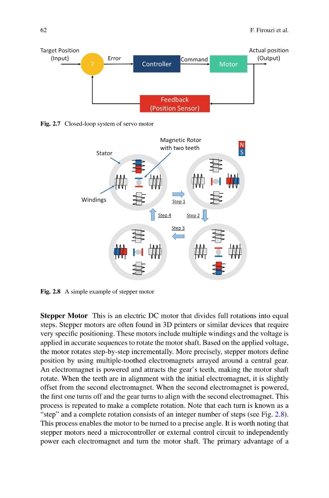
Fig. 2.7 Closed-loop system of servo motor
N
S
Windings
Magnetic Rotor
with two teeth
Stator
Step 1
Step 2
Step 3
Step 4
Fig. 2.8 A simple example of stepper motor
Stepper Motor This is an electric DC motor that divides full rotations into equal
steps. Stepper motors are often found in 3D printers or similar devices that require
very specific positioning. These motors include multiple windings and the voltage is
applied in accurate sequences to rotate the motor shaft. Based on the applied voltage,
the motor rotates step-by-step incrementally. More precisely, stepper motors define
position by using multiple-toothed electromagnets arrayed around a central gear.
An electromagnet is powered and attracts the gear’s teeth, making the motor shaft
rotate. When the teeth are in alignment with the initial electromagnet, it is slightly
offset from the second electromagnet. When the second electromagnet is powered,
the first one turns off and the gear turns to align with the second electromagnet. This
process is repeated to make a complete rotation. Note that each turn is known as a
“step” and a complete rotation consists of an integer number of steps (see Fig. 2.8).
This process enables the motor to be turned to a precise angle. It is worth noting that
stepper motors need a microcontroller or external control circuit to independently
power each electromagnet and turn the motor shaft. The primary advantage of a
F. Firouzi et al.
Controller
Motor
Feedback
(Position Sensor)
?
Target Position
(Input)
Error
Actual position
(Output)
Command
Fig. 2.7 Closed-loop system of servo motor
N
S
Windings
Magnetic Rotor
with two teeth
Stator
Step 1
Step 2
Step 3
Step 4
Fig. 2.8 A simple example of stepper motor
Stepper Motor This is an electric DC motor that divides full rotations into equal
steps. Stepper motors are often found in 3D printers or similar devices that require
very specific positioning. These motors include multiple windings and the voltage is
applied in accurate sequences to rotate the motor shaft. Based on the applied voltage,
the motor rotates step-by-step incrementally. More precisely, stepper motors define
position by using multiple-toothed electromagnets arrayed around a central gear.
An electromagnet is powered and attracts the gear’s teeth, making the motor shaft
rotate. When the teeth are in alignment with the initial electromagnet, it is slightly
offset from the second electromagnet. When the second electromagnet is powered,
the first one turns off and the gear turns to align with the second electromagnet. This
process is repeated to make a complete rotation. Note that each turn is known as a
“step” and a complete rotation consists of an integer number of steps (see Fig. 2.8).
This process enables the motor to be turned to a precise angle. It is worth noting that
stepper motors need a microcontroller or external control circuit to independently
power each electromagnet and turn the motor shaft. The primary advantage of a