

9 Emerging Hardware Technologies for IoT Data Processing
451
a0
a1
a2
a3
Z0
Z127
K0
K127
Z127
32
I
n0
n63
n63
n0
...
...
a0
a1
a2
a3
K0
K127
Z0
Z127
I
Z0
32
64
64
64
64
n127
n127
n127
n127
n63
n63
...
...
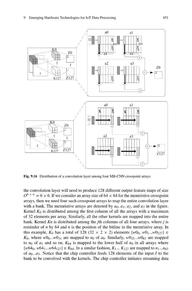
Fig. 9.16 Distribution of a convolution layer among four MB-CNN crosspoint arrays
the convolution layer will need to produce 128 different output feature maps of size
O h × w = 6 × 6. If we consider an array size of 64 × 64 for the memristive crosspoint
arrays, then we need four such crosspoint arrays to map the entire convolution layer
with a bank. The memristive arrays are denoted by a 0 , a 1 , a 2 , and a 3 in the figure.
Kernel K 0 is distributed among the first column of all the arrays with a maximum
of 32 elements per array. Similarly, all the other kernels are mapped into the entire
bank. Kernel Kn is distributed among the jth columns of all four arrays, where j is
reminder of n by 64 and n is the position of the bitline in the memristive array. In
this example, K 0 has a total of 128 (32 × 2 × 2) elements {w0 0 , w0 1 ...w0 127 } ∈
K 0 , where w0 0 ...w0 31 are mapped to n 0 of a 0 . Similarly, w0 32 ...w0 63 are mapped
to n 0 of a 1 and so on. K 64 is mapped to the lower half of n 0 in all arrays where
{w64 0 , w64 1 ...w64 127 } ∈ K 64 . In a similar fashion, K 1 ... K 127 are mapped to n 1 ...n 63
of a 0 ...a 3 . Notice that the chip controller feeds 128 elements of the input I to the
bank to be convolved with the kernels. The chip controller initiates streaming data
451
a0
a1
a2
a3
Z0
Z127
K0
K127
Z127
32
I
n0
n63
n63
n0
...
...
a0
a1
a2
a3
K0
K127
Z0
Z127
I
Z0
32
64
64
64
64
n127
n127
n127
n127
n63
n63
...
...
Fig. 9.16 Distribution of a convolution layer among four MB-CNN crosspoint arrays
the convolution layer will need to produce 128 different output feature maps of size
O h × w = 6 × 6. If we consider an array size of 64 × 64 for the memristive crosspoint
arrays, then we need four such crosspoint arrays to map the entire convolution layer
with a bank. The memristive arrays are denoted by a 0 , a 1 , a 2 , and a 3 in the figure.
Kernel K 0 is distributed among the first column of all the arrays with a maximum
of 32 elements per array. Similarly, all the other kernels are mapped into the entire
bank. Kernel Kn is distributed among the jth columns of all four arrays, where j is
reminder of n by 64 and n is the position of the bitline in the memristive array. In
this example, K 0 has a total of 128 (32 × 2 × 2) elements {w0 0 , w0 1 ...w0 127 } ∈
K 0 , where w0 0 ...w0 31 are mapped to n 0 of a 0 . Similarly, w0 32 ...w0 63 are mapped
to n 0 of a 1 and so on. K 64 is mapped to the lower half of n 0 in all arrays where
{w64 0 , w64 1 ...w64 127 } ∈ K 64 . In a similar fashion, K 1 ... K 127 are mapped to n 1 ...n 63
of a 0 ...a 3 . Notice that the chip controller feeds 128 elements of the input I to the
bank to be convolved with the kernels. The chip controller initiates streaming data