

306
S. Kirihara
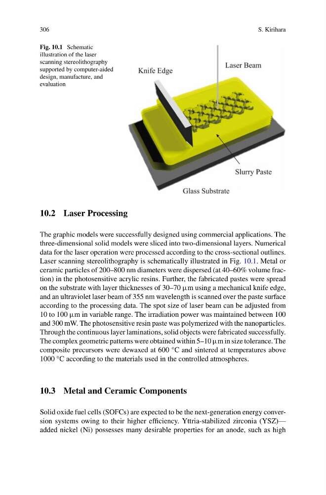
Fig. 10.1 Schematic
illustration of the laser
scanning stereolithography
supported by computer-aided
design, manufacture, and
evaluation
10.2 Laser Processing
The graphic models were successfully designed using commercial applications. The
three-dimensional solid models were sliced into two-dimensional layers. Numerical
data for the laser operation were processed according to the cross-sectional outlines.
Laser scanning stereolithography is schematically illustrated in Fig. 10.1. Metal or
ceramic particles of 200–800 nm diameters were dispersed (at 40–60% volume fraction) in the photosensitive acrylic resins. Further, the fabricated pastes were spread
on the substrate with layer thicknesses of 30–70 µm using a mechanical knife edge,
and an ultraviolet laser beam of 355 nm wavelength is scanned over the paste surface
according to the processing data. The spot size of laser beam can be adjusted from
10 to 100 µm in variable range. The irradiation power was maintained between 100
and 300 mW. The photosensitive resin paste was polymerized with the nanoparticles.
Through the continuous layer laminations, solid objects were fabricated successfully.
The complex geometric patterns were obtained within 5–10 µm in size tolerance. The
composite precursors were dewaxed at 600 °C and sintered at temperatures above
1000 °C according to the materials used in the controlled atmospheres.
10.3 Metal and Ceramic Components
Solid oxide fuel cells (SOFCs) are expected to be the next-generation energy conversion systems owing to their higher efficiency. Yttria-stabilized zirconia (YSZ)—
added nickel (Ni) possesses many desirable properties for an anode, such as high
S. Kirihara
Fig. 10.1 Schematic
illustration of the laser
scanning stereolithography
supported by computer-aided
design, manufacture, and
evaluation
10.2 Laser Processing
The graphic models were successfully designed using commercial applications. The
three-dimensional solid models were sliced into two-dimensional layers. Numerical
data for the laser operation were processed according to the cross-sectional outlines.
Laser scanning stereolithography is schematically illustrated in Fig. 10.1. Metal or
ceramic particles of 200–800 nm diameters were dispersed (at 40–60% volume fraction) in the photosensitive acrylic resins. Further, the fabricated pastes were spread
on the substrate with layer thicknesses of 30–70 µm using a mechanical knife edge,
and an ultraviolet laser beam of 355 nm wavelength is scanned over the paste surface
according to the processing data. The spot size of laser beam can be adjusted from
10 to 100 µm in variable range. The irradiation power was maintained between 100
and 300 mW. The photosensitive resin paste was polymerized with the nanoparticles.
Through the continuous layer laminations, solid objects were fabricated successfully.
The complex geometric patterns were obtained within 5–10 µm in size tolerance. The
composite precursors were dewaxed at 600 °C and sintered at temperatures above
1000 °C according to the materials used in the controlled atmospheres.
10.3 Metal and Ceramic Components
Solid oxide fuel cells (SOFCs) are expected to be the next-generation energy conversion systems owing to their higher efficiency. Yttria-stabilized zirconia (YSZ)—
added nickel (Ni) possesses many desirable properties for an anode, such as high