

262
J. Xu et al.
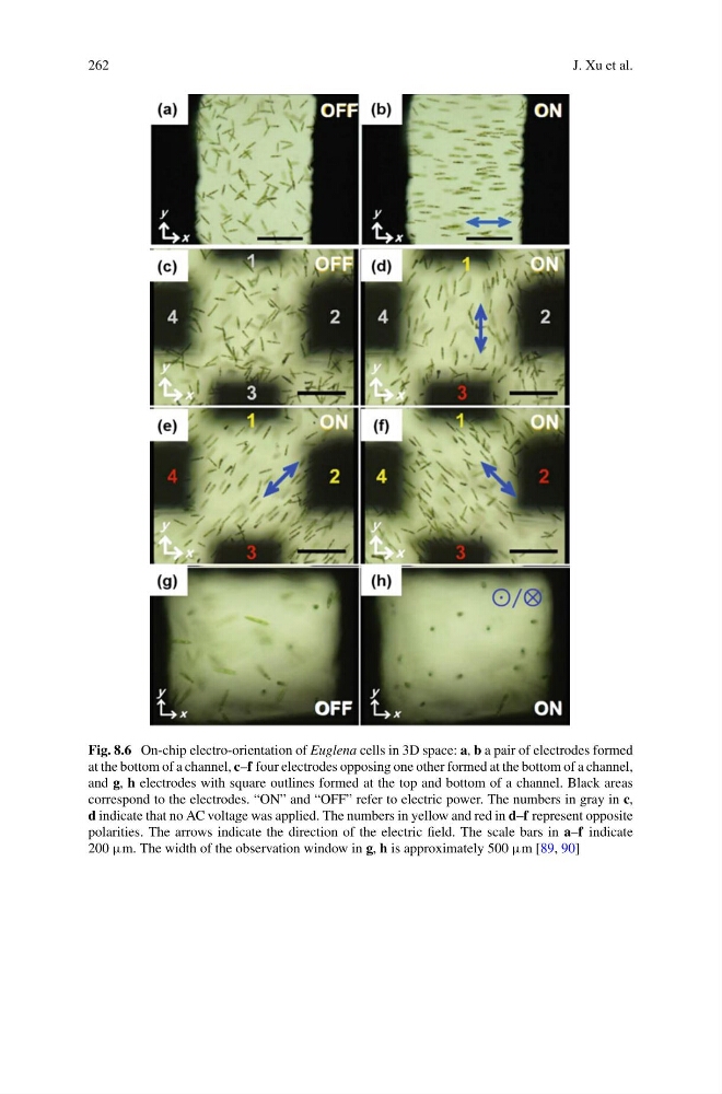
Fig. 8.6 On-chip electro-orientation of Euglena cells in 3D space: a, b a pair of electrodes formed
at the bottom of a channel, c–f four electrodes opposing one other formed at the bottom of a channel,
and g, h electrodes with square outlines formed at the top and bottom of a channel. Black areas
correspond to the electrodes. “ON” and “OFF” refer to electric power. The numbers in gray in c,
d indicate that no AC voltage was applied. The numbers in yellow and red in d–f represent opposite
polarities. The arrows indicate the direction of the electric field. The scale bars in a–f indicate
200 µm. The width of the observation window in g, h is approximately 500 µm [89, 90]
J. Xu et al.
Fig. 8.6 On-chip electro-orientation of Euglena cells in 3D space: a, b a pair of electrodes formed
at the bottom of a channel, c–f four electrodes opposing one other formed at the bottom of a channel,
and g, h electrodes with square outlines formed at the top and bottom of a channel. Black areas
correspond to the electrodes. “ON” and “OFF” refer to electric power. The numbers in gray in c,
d indicate that no AC voltage was applied. The numbers in yellow and red in d–f represent opposite
polarities. The arrows indicate the direction of the electric field. The scale bars in a–f indicate
200 µm. The width of the observation window in g, h is approximately 500 µm [89, 90]