

3.4 Case Study
47
By increasing the pressure at the inlets, also the droplet speed is increased.
Accordingly, a higher droplet speed decreases the time required by a droplet to
travel from its injection until it gets trapped. This might be crucial since the droplet
loading time is limited for some biological experiments and, therefore, the droplet
speed is an important factor for the throughput of a design.
In this design exploration, the maximal possible pressures across five pairs of
cascaded trapping wells are explored (cf. in the design of [13] also five pairs of
trapping wells are cascaded). Again, the pressures are increased until any objective
is violated. The simulation results reveal that Objective 2 limits the maximal
pressures. More precisely, for too high pressures, the simulation predicts that the
pressure across the trapping well and the narrow gaps exceeds the Laplace pressure,
which would cause a droplet to be squeezed out of the trap.
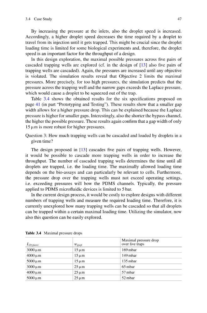
Table 3.4 shows the obtained results for the six specifications proposed on
page 41 (in part “Prototyping and Testing”). These results show that a smaller gap
width allows for a higher pressure drop. This can be explained because the Laplace
pressure is higher for smaller gaps. Interestingly, also the shorter the bypass channel,
the higher the possible pressure. These results again confirm that a gap width of only
15 μm is more robust for higher pressures.
Question 3: How much trapping wells can be cascaded and loaded by droplets in a
given time?
The design proposed in [13] cascades five pairs of trapping wells. However,
it would be possible to cascade more trapping wells in order to increase the
throughput. The number of cascaded trapping wells determines the time until all
droplets are trapped, i.e. the loading time. The maximally allowed loading time
depends on the bio-assays and can particularly be relevant to cells. Furthermore,
the pressure drop over the trapping wells must not exceed operating settings,
i.e. exceeding pressures will bow the PDMS channels. Typically, the pressure
applied to PDMS microfluidic devices is limited to 5 bar.
In the current design process, it would be costly to explore designs with different
numbers of trapping wells and measure the required loading time. Therefore, it is
currently unexplored how many trapping wells can be cascaded so that all droplets
can be trapped within a certain maximal loading time. Utilizing the simulator, now
also this question can be easily explored.
Table 3.4 Maximal pressure drops
Maximal pressure drop
L bypass
w gap
over five traps
3000 μm
15 μm
169 mbar
4000 μm
15 μm
149 mbar
5000 μm
15 μm
135 mbar
3000 μm
25 μm
65 mbar
4000 μm
25 μm
57 mbar
5000 μm
25 μm
52 mbar
47
By increasing the pressure at the inlets, also the droplet speed is increased.
Accordingly, a higher droplet speed decreases the time required by a droplet to
travel from its injection until it gets trapped. This might be crucial since the droplet
loading time is limited for some biological experiments and, therefore, the droplet
speed is an important factor for the throughput of a design.
In this design exploration, the maximal possible pressures across five pairs of
cascaded trapping wells are explored (cf. in the design of [13] also five pairs of
trapping wells are cascaded). Again, the pressures are increased until any objective
is violated. The simulation results reveal that Objective 2 limits the maximal
pressures. More precisely, for too high pressures, the simulation predicts that the
pressure across the trapping well and the narrow gaps exceeds the Laplace pressure,
which would cause a droplet to be squeezed out of the trap.
Table 3.4 shows the obtained results for the six specifications proposed on
page 41 (in part “Prototyping and Testing”). These results show that a smaller gap
width allows for a higher pressure drop. This can be explained because the Laplace
pressure is higher for smaller gaps. Interestingly, also the shorter the bypass channel,
the higher the possible pressure. These results again confirm that a gap width of only
15 μm is more robust for higher pressures.
Question 3: How much trapping wells can be cascaded and loaded by droplets in a
given time?
The design proposed in [13] cascades five pairs of trapping wells. However,
it would be possible to cascade more trapping wells in order to increase the
throughput. The number of cascaded trapping wells determines the time until all
droplets are trapped, i.e. the loading time. The maximally allowed loading time
depends on the bio-assays and can particularly be relevant to cells. Furthermore,
the pressure drop over the trapping wells must not exceed operating settings,
i.e. exceeding pressures will bow the PDMS channels. Typically, the pressure
applied to PDMS microfluidic devices is limited to 5 bar.
In the current design process, it would be costly to explore designs with different
numbers of trapping wells and measure the required loading time. Therefore, it is
currently unexplored how many trapping wells can be cascaded so that all droplets
can be trapped within a certain maximal loading time. Utilizing the simulator, now
also this question can be easily explored.
Table 3.4 Maximal pressure drops
Maximal pressure drop
L bypass
w gap
over five traps
3000 μm
15 μm
169 mbar
4000 μm
15 μm
149 mbar
5000 μm
15 μm
135 mbar
3000 μm
25 μm
65 mbar
4000 μm
25 μm
57 mbar
5000 μm
25 μm
52 mbar