

28
3 Simulating Droplet Microfluidic Networks
l c in [μm] R c in [mbar/(μl/min)]
c 1
660
46.32
c 2
594
41.69
c 3
990
69.48
c 4
594
41.69
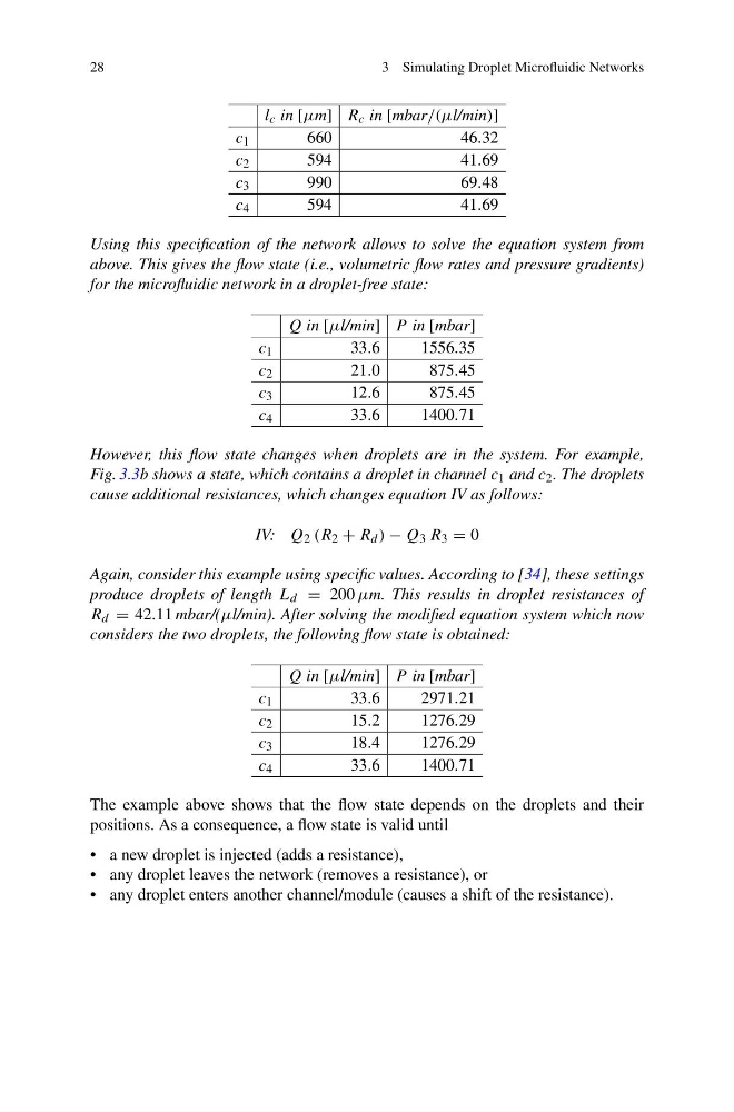
Using this specification of the network allows to solve the equation system from
above. This gives the flow state (i.e., volumetric flow rates and pressure gradients)
for the microfluidic network in a droplet-free state:
Q in [μl/min] P in [mbar]
c 1
33.6
1556.35
c 2
21.0
875.45
c 3
12.6
875.45
c 4
33.6
1400.71
However, this flow state changes when droplets are in the system. For example,
Fig. 3.3b shows a state, which contains a droplet in channel c 1 and c 2 . The droplets
cause additional resistances, which changes equation IV as follows:
IV: Q 2 (R 2 + R d ) − Q 3 R 3 = 0
Again, consider this example using specific values. According to [34], these settings
produce droplets of length L d = 200 μm. This results in droplet resistances of
R d = 42.11 mbar/(μl/min). After solving the modified equation system which now
considers the two droplets, the following flow state is obtained:
Q in [μl/min] P in [mbar]
c 1
33.6
2971.21
c 2
15.2
1276.29
c 3
18.4
1276.29
c 4
33.6
1400.71
The example above shows that the flow state depends on the droplets and their
positions. As a consequence, a flow state is valid until
• a new droplet is injected (adds a resistance),
• any droplet leaves the network (removes a resistance), or
• any droplet enters another channel/module (causes a shift of the resistance).
3 Simulating Droplet Microfluidic Networks
l c in [μm] R c in [mbar/(μl/min)]
c 1
660
46.32
c 2
594
41.69
c 3
990
69.48
c 4
594
41.69
Using this specification of the network allows to solve the equation system from
above. This gives the flow state (i.e., volumetric flow rates and pressure gradients)
for the microfluidic network in a droplet-free state:
Q in [μl/min] P in [mbar]
c 1
33.6
1556.35
c 2
21.0
875.45
c 3
12.6
875.45
c 4
33.6
1400.71
However, this flow state changes when droplets are in the system. For example,
Fig. 3.3b shows a state, which contains a droplet in channel c 1 and c 2 . The droplets
cause additional resistances, which changes equation IV as follows:
IV: Q 2 (R 2 + R d ) − Q 3 R 3 = 0
Again, consider this example using specific values. According to [34], these settings
produce droplets of length L d = 200 μm. This results in droplet resistances of
R d = 42.11 mbar/(μl/min). After solving the modified equation system which now
considers the two droplets, the following flow state is obtained:
Q in [μl/min] P in [mbar]
c 1
33.6
2971.21
c 2
15.2
1276.29
c 3
18.4
1276.29
c 4
33.6
1400.71
The example above shows that the flow state depends on the droplets and their
positions. As a consequence, a flow state is valid until
• a new droplet is injected (adds a resistance),
• any droplet leaves the network (removes a resistance), or
• any droplet enters another channel/module (causes a shift of the resistance).