

106
8 Generating Droplet Sequences
Overall, the results show that the proposed model is a suitable representation
for the droplet flow in microfluidic networks including the passive droplet routing
mechanism. Hence, this discrete model provides the basis for the automatic methods
for generating droplet sequences. These automatic methods are presented next.
8.2 Droplet Sequence Generation
A droplet sequence has to route a payload along a dedicated path through a
microfluidic network, which, eventually, executes the experiment. More precisely,
the path of the payload is predefined by the experiment to be executed. This path
defines the bifurcations where the payload does flow along non-default successors
and, hence, defines when the default successor has to be blocked by a header. In
order to get a header blocking a default successor, multiple potential paths can be
considered. Moreover, when a header takes a path which also contains non-default
successors at bifurcations, additional headers are required, i.e. headers are required
to route other headers. The following example illustrates the required headers and
their paths.
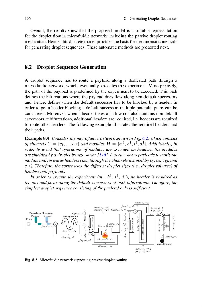
Example 8.4 Consider the microfluidic network shown in Fig. 8.2, which consists
of channels C = {c 1 , . . . c 19 } and modules M = {m 1 , h 1 , t 1 , d 1 }. Additionally, in
order to avoid that operations of modules are executed on headers, the modules
are shielded by a droplet by size sorter [116]. A sorter steers payloads towards the
module and forwards headers (i.e., through the channels denoted by c 2 , c 8 , c 15 , and
c 18 ). Therefore, the sorter uses the different droplet sizes (i.e., droplet volumes) of
headers and payloads.
In order to execute the experiment (m 1 , h 1 , t 1 , d 1 ), no header is required as
the payload flows along the default successors at both bifurcations. Therefore, the
simplest droplet sequence consisting of the payload only is sufficient.
)=14
c
15
c
16
c
13
c
3
c
4
c
5
c
6
c
10
c
12
c
11
c
m
19
c
7
c
14
c
2
c
8
c
9
c
18
c
Pump
1
)=175
Detecting Module
1
pSteps(d
17
Delaying Module
S
S
Heating Module
Bypass Channel
Bypass Channel
)=2
S
pSteps(h 1
Payloads on
Demand
1
c 1
)=2
Headers on
Demand
)=3
1
_Steps(c
4
_Steps(c
6
_Steps(c )=2
)=32
8
hSteps(c
)=4
5
_Steps(c
_Steps(c
11
15
hSteps(c )=32
)=170
)=171
Waste Chamber
_Steps(c 19 )=2
hSteps(c
18
)=2
pSteps(t
)=4
hSteps(c 2 )=26
pSteps(m 1
_Steps(c 17 )=2
_Steps(c 16 )=2
S
_Steps(c 10 )=2
1
h
1
t
1
d
7
pSteps(c
7
hSteps(c
)=14
Mixing Module
)=2
)=171
)=170
)=3
_Steps(c
12
)=18
_Steps(c 9
_Steps(c 13
hSteps(c
pSteps(c 14
14
)=26
_Steps(c 3
Fig. 8.2 Microfluidic network supporting passive droplet routing
8 Generating Droplet Sequences
Overall, the results show that the proposed model is a suitable representation
for the droplet flow in microfluidic networks including the passive droplet routing
mechanism. Hence, this discrete model provides the basis for the automatic methods
for generating droplet sequences. These automatic methods are presented next.
8.2 Droplet Sequence Generation
A droplet sequence has to route a payload along a dedicated path through a
microfluidic network, which, eventually, executes the experiment. More precisely,
the path of the payload is predefined by the experiment to be executed. This path
defines the bifurcations where the payload does flow along non-default successors
and, hence, defines when the default successor has to be blocked by a header. In
order to get a header blocking a default successor, multiple potential paths can be
considered. Moreover, when a header takes a path which also contains non-default
successors at bifurcations, additional headers are required, i.e. headers are required
to route other headers. The following example illustrates the required headers and
their paths.
Example 8.4 Consider the microfluidic network shown in Fig. 8.2, which consists
of channels C = {c 1 , . . . c 19 } and modules M = {m 1 , h 1 , t 1 , d 1 }. Additionally, in
order to avoid that operations of modules are executed on headers, the modules
are shielded by a droplet by size sorter [116]. A sorter steers payloads towards the
module and forwards headers (i.e., through the channels denoted by c 2 , c 8 , c 15 , and
c 18 ). Therefore, the sorter uses the different droplet sizes (i.e., droplet volumes) of
headers and payloads.
In order to execute the experiment (m 1 , h 1 , t 1 , d 1 ), no header is required as
the payload flows along the default successors at both bifurcations. Therefore, the
simplest droplet sequence consisting of the payload only is sufficient.
)=14
c
15
c
16
c
13
c
3
c
4
c
5
c
6
c
10
c
12
c
11
c
m
19
c
7
c
14
c
2
c
8
c
9
c
18
c
Pump
1
)=175
Detecting Module
1
pSteps(d
17
Delaying Module
S
S
Heating Module
Bypass Channel
Bypass Channel
)=2
S
pSteps(h 1
Payloads on
Demand
1
c 1
)=2
Headers on
Demand
)=3
1
_Steps(c
4
_Steps(c
6
_Steps(c )=2
)=32
8
hSteps(c
)=4
5
_Steps(c
_Steps(c
11
15
hSteps(c )=32
)=170
)=171
Waste Chamber
_Steps(c 19 )=2
hSteps(c
18
)=2
pSteps(t
)=4
hSteps(c 2 )=26
pSteps(m 1
_Steps(c 17 )=2
_Steps(c 16 )=2
S
_Steps(c 10 )=2
1
h
1
t
1
d
7
pSteps(c
7
hSteps(c
)=14
Mixing Module
)=2
)=171
)=170
)=3
_Steps(c
12
)=18
_Steps(c 9
_Steps(c 13
hSteps(c
pSteps(c 14
14
)=26
_Steps(c 3
Fig. 8.2 Microfluidic network supporting passive droplet routing