

256
24 The Michelson Experiment
-
6
6
?
M 1
M 2
*
Σ o :
S
l 1
l 2
P
a)
;
M 1
6
?
-
M 2 l 2
l 1
* S
P @
@
b)
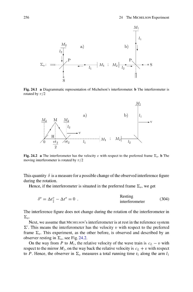
Fig. 24.1 a Diagrammatic representation of Michelson’s interferometer. b The interferometer is
rotated by π/2
a)
0
M 1
M 2
M 2
M
H
vt 2
vt 2
2
l 2
l 1
v
;
J
J ^
-
J
J
J
b)
M 2
@
@
- v
M 1
l 2
l 1
Fig. 24.2 a The interferometer has the velocity v with respect to the preferred frame o . b The
moving interferometer is rotated by π/2
This quantity δ is a measure for a possible change of the observed interference figure
during the rotation.
Hence, if the interferometer is situated in the preferred frame o , we get
δ
o
=
o
π
2
−
o
= 0 .
Resting
interferometer
(304)
The interference figure does not change during the rotation of the interferometer in
o .
Next, we assume that Michelson’s interferometer is at rest in the reference system
. This means the interferometer has the velocity v with respect to the preferred
frame o . This experiment, as the other before, is observed and described by an
observer resting in o , see Fig. 24.2.
On the way from P to M 1 , the relative velocity of the wave train is c L − v with
respect to the mirror M 1 , on the way back the relative velocity is c L + v with respect
to P. Hence, the observer in o measures a total running time t 1 along the arm l 1
24 The Michelson Experiment
-
6
6
?
M 1
M 2
*
Σ o :
S
l 1
l 2
P
a)
;
M 1
6
?
-
M 2 l 2
l 1
* S
P @
@
b)
Fig. 24.1 a Diagrammatic representation of Michelson’s interferometer. b The interferometer is
rotated by π/2
a)
0
M 1
M 2
M 2
M
H
vt 2
vt 2
2
l 2
l 1
v
;
J
J ^
-
J
J
J
b)
M 2
@
@
- v
M 1
l 2
l 1
Fig. 24.2 a The interferometer has the velocity v with respect to the preferred frame o . b The
moving interferometer is rotated by π/2
This quantity δ is a measure for a possible change of the observed interference figure
during the rotation.
Hence, if the interferometer is situated in the preferred frame o , we get
δ
o
=
o
π
2
−
o
= 0 .
Resting
interferometer
(304)
The interference figure does not change during the rotation of the interferometer in
o .
Next, we assume that Michelson’s interferometer is at rest in the reference system
. This means the interferometer has the velocity v with respect to the preferred
frame o . This experiment, as the other before, is observed and described by an
observer resting in o , see Fig. 24.2.
On the way from P to M 1 , the relative velocity of the wave train is c L − v with
respect to the mirror M 1 , on the way back the relative velocity is c L + v with respect
to P. Hence, the observer in o measures a total running time t 1 along the arm l 1