

18 The Doppler Effect
207
as we have already discussed in Chap. 11. If we ignore these facts, then we slip into
the paradox described in Chap. 11.
In order to describe the experimental situation, we choose an arbitrary reference
system o (after which this reference system is our norm) in which emitter and
observer are alternatively situated and examine the above-described cases in the
same sequence.
(I) Observer O rests in the reference system o in which we designate the space
and time coordinates as x and t . Emitter S moves towards the observer with the
positive velocity v. An observer S on top of the standard emitter S is at rest in a
reference system
, which possesses the velocity −v when observed from o . The
space and time coordinates in
are designated as x
and t
, see Fig. 18.6. Observer
S controls the frequency ν o of his emitter in his reference system
. He therefore
counts the number n o of oscillations during the time interval t
shown by his clock
and finds ν o = n o //t
, or a period of oscillation T o for the membrane according to
T o =
1
ν o
=
t
n o
.
(234)
An internal observer S on emitter S sees that he produces a new wave crest in
space every T o seconds (or in any other time unit, for example lattice seconds, see
Eq. (91)). However, observer O resting in o determines that S’s clock in
goes
behind according to our Eq. (121) (here, we write c T in the place of c o ). Therefore,
when emitter S’s clock reads T o seconds and the next wave crest is emitted, observer
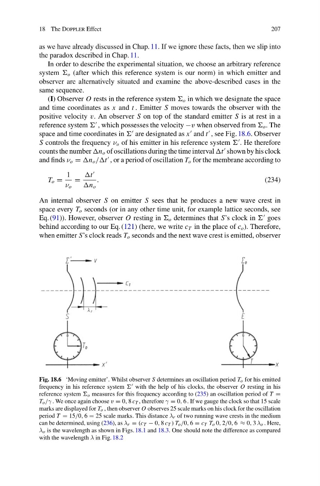
Fig. 18.6 ‘Moving emitter’. Whilst observer S determines an oscillation period T o for his emitted
frequency in his reference system with the help of his clocks, the observer O resting in his
reference system o measures for this frequency according to (235) an oscillation period of T =
T o /γ . We once again choose v = 0, 8 c T , therefore γ = 0, 6 . If we gauge the clock so that 15 scale
marks are displayed for T o , then observer O observes 25 scale marks on his clock for the oscillation
period T = 15/0, 6 = 25 scale marks. This distance λ r of two running wave crests in the medium
can be determined, using (236), as λ r = (c T − 0, 8 c T ) T o /0, 6 = c T T o 0, 2/0, 6 ≈ 0, 3 λ o . Here,
λ o is the wavelength as shown in Figs. 18.1 and 18.3. One should note the difference as compared
with the wavelength λ in Fig. 18.2
207
as we have already discussed in Chap. 11. If we ignore these facts, then we slip into
the paradox described in Chap. 11.
In order to describe the experimental situation, we choose an arbitrary reference
system o (after which this reference system is our norm) in which emitter and
observer are alternatively situated and examine the above-described cases in the
same sequence.
(I) Observer O rests in the reference system o in which we designate the space
and time coordinates as x and t . Emitter S moves towards the observer with the
positive velocity v. An observer S on top of the standard emitter S is at rest in a
reference system
, which possesses the velocity −v when observed from o . The
space and time coordinates in
are designated as x
and t
, see Fig. 18.6. Observer
S controls the frequency ν o of his emitter in his reference system
. He therefore
counts the number n o of oscillations during the time interval t
shown by his clock
and finds ν o = n o //t
, or a period of oscillation T o for the membrane according to
T o =
1
ν o
=
t
n o
.
(234)
An internal observer S on emitter S sees that he produces a new wave crest in
space every T o seconds (or in any other time unit, for example lattice seconds, see
Eq. (91)). However, observer O resting in o determines that S’s clock in
goes
behind according to our Eq. (121) (here, we write c T in the place of c o ). Therefore,
when emitter S’s clock reads T o seconds and the next wave crest is emitted, observer
Fig. 18.6 ‘Moving emitter’. Whilst observer S determines an oscillation period T o for his emitted
frequency in his reference system with the help of his clocks, the observer O resting in his
reference system o measures for this frequency according to (235) an oscillation period of T =
T o /γ . We once again choose v = 0, 8 c T , therefore γ = 0, 6 . If we gauge the clock so that 15 scale
marks are displayed for T o , then observer O observes 25 scale marks on his clock for the oscillation
period T = 15/0, 6 = 25 scale marks. This distance λ r of two running wave crests in the medium
can be determined, using (236), as λ r = (c T − 0, 8 c T ) T o /0, 6 = c T T o 0, 2/0, 6 ≈ 0, 3 λ o . Here,
λ o is the wavelength as shown in Figs. 18.1 and 18.3. One should note the difference as compared
with the wavelength λ in Fig. 18.2