

10 Measuring-Rods and Clocks in Motion
103
6
q
t
x =0
x
q
III
oo (0, t)
q
III
(vt, t)
U 1
U 2
U v
`
`
`
`
` ` `
`
`
`
`
`
` ` `
`
-
t
t
t
-
` ``
`
`
`
`
` ` `
`
6
v
q
t
x = vt
x
a
2
a
2
T o
T o
T
=
5
3 T o
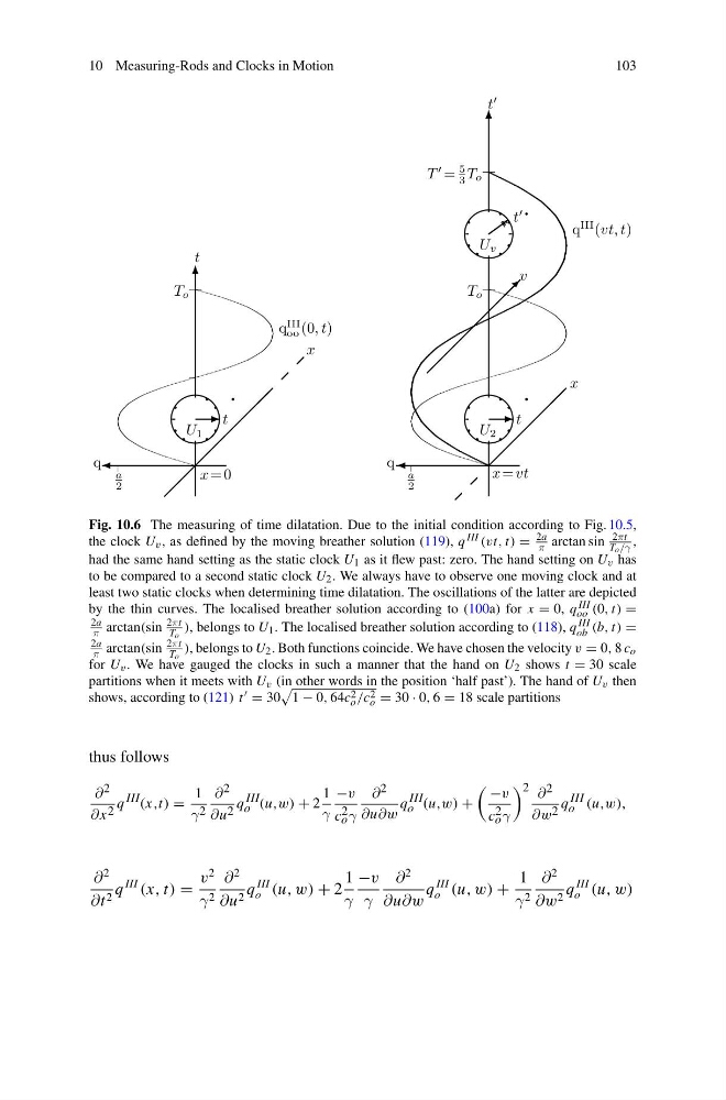
Fig. 10.6 The measuring of time dilatation. Due to the initial condition according to Fig. 10.5,
the clock U v , as defined by the moving breather solution (119), q III (vt, t) =
2a
π arctan sin
2πt
To/γ ,
had the same hand setting as the static clock U 1 as it flew past: zero. The hand setting on U v has
to be compared to a second static clock U 2 . We always have to observe one moving clock and at
least two static clocks when determining time dilatation. The oscillations of the latter are depicted
by the thin curves. The localised breather solution according to (100a) for x = 0, q III
oo (0, t) =
2a
π arctan(sin
2πt
To ), belongs to U 1 . The localised breather solution according to (118), q III
ob (b, t) =
2a
π arctan(sin
2πt
To ), belongs to U 2 . Both functions coincide. We have chosen the velocity v = 0, 8 c o
for U v . We have gauged the clocks in such a manner that the hand on U 2 shows t = 30 scale
partitions when it meets with U v (in other words in the position ‘half past’). The hand of U v then
shows, according to (121) t = 30
1 − 0, 64c 2
o /c 2
o = 30 · 0, 6 = 18 scale partitions
thus follows
∂ 2
∂x 2 q III (x,t) =
1
γ 2
∂ 2
∂u 2 q III
o (u,w) + 2
1
γ
−v
c 2
o γ
∂ 2
∂u∂w
q III
o (u,w) +
−v
c 2
o γ
2 ∂ 2
∂w 2 q III
o (u,w),
∂
2
∂t 2 q
III
(x, t) =
v
2
γ 2
∂
2
∂u 2 q
III
o (u, w) + 2
1
γ
−v
γ
∂
2
∂u∂w
q
III
o (u, w) +
1
γ 2
∂
2
∂w 2 q
III
o (u, w)
103
6
q
t
x =0
x
q
III
oo (0, t)
q
III
(vt, t)
U 1
U 2
U v
`
`
`
`
` ` `
`
`
`
`
`
` ` `
`
-
t
t
t
-
` ``
`
`
`
`
` ` `
`
6
v
q
t
x = vt
x
a
2
a
2
T o
T o
T
=
5
3 T o
Fig. 10.6 The measuring of time dilatation. Due to the initial condition according to Fig. 10.5,
the clock U v , as defined by the moving breather solution (119), q III (vt, t) =
2a
π arctan sin
2πt
To/γ ,
had the same hand setting as the static clock U 1 as it flew past: zero. The hand setting on U v has
to be compared to a second static clock U 2 . We always have to observe one moving clock and at
least two static clocks when determining time dilatation. The oscillations of the latter are depicted
by the thin curves. The localised breather solution according to (100a) for x = 0, q III
oo (0, t) =
2a
π arctan(sin
2πt
To ), belongs to U 1 . The localised breather solution according to (118), q III
ob (b, t) =
2a
π arctan(sin
2πt
To ), belongs to U 2 . Both functions coincide. We have chosen the velocity v = 0, 8 c o
for U v . We have gauged the clocks in such a manner that the hand on U 2 shows t = 30 scale
partitions when it meets with U v (in other words in the position ‘half past’). The hand of U v then
shows, according to (121) t = 30
1 − 0, 64c 2
o /c 2
o = 30 · 0, 6 = 18 scale partitions
thus follows
∂ 2
∂x 2 q III (x,t) =
1
γ 2
∂ 2
∂u 2 q III
o (u,w) + 2
1
γ
−v
c 2
o γ
∂ 2
∂u∂w
q III
o (u,w) +
−v
c 2
o γ
2 ∂ 2
∂w 2 q III
o (u,w),
∂
2
∂t 2 q
III
(x, t) =
v
2
γ 2
∂
2
∂u 2 q
III
o (u, w) + 2
1
γ
−v
γ
∂
2
∂u∂w
q
III
o (u, w) +
1
γ 2
∂
2
∂w 2 q
III
o (u, w)