

25
Fundamentals of Electric Capacitors
0
V −t/τ
I =
e
L
(1.44)
R
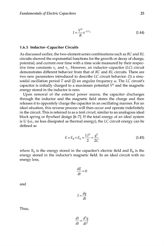
1.6.5 Inductor–Capacitor Circuits
As discussed earlier, the two-element series combinations such as RC and RL
circuits showed the exponential functions for the growth or decay of charge,
potential, and current over time with a time scale measured by their respective time constants τ C and τ L . However, an inductor–capacitor (LC) circuit
demonstrates different behavior from that of RC and RL circuits. There are
two new parameters introduced to describe LC circuit behavior: (1) a sinusoidal oscillation period T and (2) an angular frequency ω. The LC circuit’s
capacitor is initially charged to a maximum potential V 0 and the magnetic
energy stored in the inductor is zero.
Upon removal of the external power source, the capacitor discharges
through the inductor and the magnetic field stores the charge and then
releases it to oppositely charge the capacitor in an oscillating manner. For an
ideal situation, this reverse process will then occur and operate indefinitely
in the circuit. This is referred to as a tank circuit, similar to an analogous ideal
block spring or flywheel design [6–7]. If the total energy of an ideal system
is U (i.e., no loss dissipated as thermal energy), the LC circuit energy can be
defined as
LI
2
q
2
E E B + E E
(1.45)
=
=
+
2 2C
where E E is the energy stored in the capacitor’s electric field and E B is the
energy stored in the inductor’s magnetic field. In an ideal circuit with no
energy loss,
dE = 0
dt
and
dq
I =
dt
Thus,
2
dI d q
=
dt dt
2
Fundamentals of Electric Capacitors
0
V −t/τ
I =
e
L
(1.44)
R
1.6.5 Inductor–Capacitor Circuits
As discussed earlier, the two-element series combinations such as RC and RL
circuits showed the exponential functions for the growth or decay of charge,
potential, and current over time with a time scale measured by their respective time constants τ C and τ L . However, an inductor–capacitor (LC) circuit
demonstrates different behavior from that of RC and RL circuits. There are
two new parameters introduced to describe LC circuit behavior: (1) a sinusoidal oscillation period T and (2) an angular frequency ω. The LC circuit’s
capacitor is initially charged to a maximum potential V 0 and the magnetic
energy stored in the inductor is zero.
Upon removal of the external power source, the capacitor discharges
through the inductor and the magnetic field stores the charge and then
releases it to oppositely charge the capacitor in an oscillating manner. For an
ideal situation, this reverse process will then occur and operate indefinitely
in the circuit. This is referred to as a tank circuit, similar to an analogous ideal
block spring or flywheel design [6–7]. If the total energy of an ideal system
is U (i.e., no loss dissipated as thermal energy), the LC circuit energy can be
defined as
LI
2
q
2
E E B + E E
(1.45)
=
=
+
2 2C
where E E is the energy stored in the capacitor’s electric field and E B is the
energy stored in the inductor’s magnetic field. In an ideal circuit with no
energy loss,
dE = 0
dt
and
dq
I =
dt
Thus,
2
dI d q
=
dt dt
2