

+ V d –
+ V d –
i L
i L
Load
i b
i b
i c
– V s +
V uc
Load
R b
V b
+
+
–
R b
V b
+
–
–
i c
V uc
+
–
V c
R c
+
–
V c
R c
+
–
Option 1
Option 2
270
Electrochemical Supercapacitors for Energy Storage and Delivery
limits its lifetime. Therefore, these options must be weighed by a designer in
accordance with applied constraints.
Optimizing an ESS involves minimizing the costs of the system while
maximizing its efficiency. To quantify this objective, Kazerani [16] used a
function (f obj ):
f obj = a · x · Eff – b · Cost – y · c · Mass
(6.1)
where a, b, and c are weight coefficients representative of the importance of
improving efficiency and reducing the costs and mass, and x and y are the
parameters used to scale the compared quantities, respectively. Each parameter is related such that a + b + c = 1. The Eff term representing efficiency
is derived by combining the efficiency calculated from the acceleration and
regeneration phases of operation. Maximizing the objective function can
be achieved by implementation of a nonlinear method using appropriate
numerical solution software.
Through the use of the ADVISOR program noted earlier, the overall power
requirements of a specific motor and drive cycle for a vehicle can be determined. From implementation of the model in the program, the ESS power
component that generally includes the peak power and higher frequency
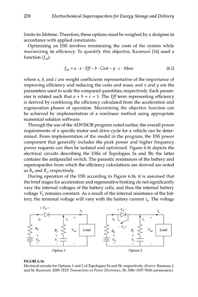
power requests can then be isolated and optimized. Figure 6.16 depicts the
electrical circuits describing the ESSs of Topologies 5a and 5b; the latter
contains the antiparallel switch. The parasitic resistances of the battery and
supercapacitor from which the efficiency calculations are derived are noted
as R b and R c , respectively.
During operation of the ESS according to Figure 6.16, it is assumed that
the brief stages for acceleration and regenerative braking do not significantly
vary the internal voltages of the battery cells, and thus the internal battery
voltage V b remains constant. As a result of the internal resistance of the battery, the terminal voltage will vary with the battery current i b . The voltage
FIGURE 6.16
Electrical circuits for Options 1 and 2 of Topologies 5a and 5b, respectively. (Source: Bauman, J.
and M. Kazerani. 2009. IEEE Transactions on Power Electronics, 58, 3186–3197. With permission.)
+ V d –
i L
i L
Load
i b
i b
i c
– V s +
V uc
Load
R b
V b
+
+
–
R b
V b
+
–
–
i c
V uc
+
–
V c
R c
+
–
V c
R c
+
–
Option 1
Option 2
270
Electrochemical Supercapacitors for Energy Storage and Delivery
limits its lifetime. Therefore, these options must be weighed by a designer in
accordance with applied constraints.
Optimizing an ESS involves minimizing the costs of the system while
maximizing its efficiency. To quantify this objective, Kazerani [16] used a
function (f obj ):
f obj = a · x · Eff – b · Cost – y · c · Mass
(6.1)
where a, b, and c are weight coefficients representative of the importance of
improving efficiency and reducing the costs and mass, and x and y are the
parameters used to scale the compared quantities, respectively. Each parameter is related such that a + b + c = 1. The Eff term representing efficiency
is derived by combining the efficiency calculated from the acceleration and
regeneration phases of operation. Maximizing the objective function can
be achieved by implementation of a nonlinear method using appropriate
numerical solution software.
Through the use of the ADVISOR program noted earlier, the overall power
requirements of a specific motor and drive cycle for a vehicle can be determined. From implementation of the model in the program, the ESS power
component that generally includes the peak power and higher frequency
power requests can then be isolated and optimized. Figure 6.16 depicts the
electrical circuits describing the ESSs of Topologies 5a and 5b; the latter
contains the antiparallel switch. The parasitic resistances of the battery and
supercapacitor from which the efficiency calculations are derived are noted
as R b and R c , respectively.
During operation of the ESS according to Figure 6.16, it is assumed that
the brief stages for acceleration and regenerative braking do not significantly
vary the internal voltages of the battery cells, and thus the internal battery
voltage V b remains constant. As a result of the internal resistance of the battery, the terminal voltage will vary with the battery current i b . The voltage
FIGURE 6.16
Electrical circuits for Options 1 and 2 of Topologies 5a and 5b, respectively. (Source: Bauman, J.
and M. Kazerani. 2009. IEEE Transactions on Power Electronics, 58, 3186–3197. With permission.)