

267
Coupling with Batteries and Fuel Cells
to the inverter or motor. The converter enables a means of controlling the
power supplied by the battery. Indirect control of the supercapacitor power
is subsequently provided as the difference in power required by the inverter
and that provided by the battery and FC. Disadvantages to this topology
include the additional costs associated with a second converter and the inefficient means of recharging the battery.
High power converters are inefficient at low load operations, but high current recharging of the battery induces I 2 R losses related to the internal resistance of the battery. Furthermore, the power to recharge the battery derived
from the FC must travel through two DC–DC converters, causing further
efficiency losses. Therefore, while control is implemented in Topology 2, it
provides an inefficient means of recharging the battery.
Topology 3 is similar in principle to Topology 2 in which the supercapacitor rather than the battery is connected to the high voltage bus line via a
bidirectional DC–DC converter. This strategy imparts similar benefits and
disadvantages as Topology 2 regarding full power control of each system
in exchange for higher costs, additional power losses, and increased system
mass. This system presents the case reiterated throughout the chapter regarding a choice between improved control and efficiency. The additional DC–DC
converter may be optimized in both Topology 2 and Topology 3, depending
on the sizes of the battery and supercapacitor. However, the strength of the
former lies in using the battery less often to extend its lifetime, while the latter provides better control of the supercapacitor for its intended continuous
use, thus improving the charging efficiency of the battery.
In Topology 4, a bidirectional DC–DC converter is connected between both
the battery and supercapacitor to further increase the costs and mass of the
system. This topology is generally undesirable in comparison to the previous
three, with the additional converter proving no significant advantage.
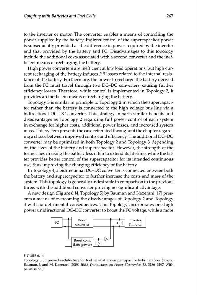
A new design (Figure 6.14, Topology 5) by Bauman and Kazerani [17] presents a means of overcoming the disadvantages of Topology 2 and Topology
3 with no detrimental consequences. This topology incorporates one high
power unidirectional DC–DC converter to boost the FC voltage, while a more
FC
B
Boost
converter
Inverter
& motor
UC
Boost conv.
(Low power)
FIGURE 6.14
Topology 5: Improved architecture for fuel cell–battery–supercapacitor hybridization. (Source:
Bauman, J. and M. Kazerani. 2008. IEEE Transactions on Power Electronics, 58, 3186–3197. With
permission.)
Coupling with Batteries and Fuel Cells
to the inverter or motor. The converter enables a means of controlling the
power supplied by the battery. Indirect control of the supercapacitor power
is subsequently provided as the difference in power required by the inverter
and that provided by the battery and FC. Disadvantages to this topology
include the additional costs associated with a second converter and the inefficient means of recharging the battery.
High power converters are inefficient at low load operations, but high current recharging of the battery induces I 2 R losses related to the internal resistance of the battery. Furthermore, the power to recharge the battery derived
from the FC must travel through two DC–DC converters, causing further
efficiency losses. Therefore, while control is implemented in Topology 2, it
provides an inefficient means of recharging the battery.
Topology 3 is similar in principle to Topology 2 in which the supercapacitor rather than the battery is connected to the high voltage bus line via a
bidirectional DC–DC converter. This strategy imparts similar benefits and
disadvantages as Topology 2 regarding full power control of each system
in exchange for higher costs, additional power losses, and increased system
mass. This system presents the case reiterated throughout the chapter regarding a choice between improved control and efficiency. The additional DC–DC
converter may be optimized in both Topology 2 and Topology 3, depending
on the sizes of the battery and supercapacitor. However, the strength of the
former lies in using the battery less often to extend its lifetime, while the latter provides better control of the supercapacitor for its intended continuous
use, thus improving the charging efficiency of the battery.
In Topology 4, a bidirectional DC–DC converter is connected between both
the battery and supercapacitor to further increase the costs and mass of the
system. This topology is generally undesirable in comparison to the previous
three, with the additional converter proving no significant advantage.
A new design (Figure 6.14, Topology 5) by Bauman and Kazerani [17] presents a means of overcoming the disadvantages of Topology 2 and Topology
3 with no detrimental consequences. This topology incorporates one high
power unidirectional DC–DC converter to boost the FC voltage, while a more
FC
B
Boost
converter
Inverter
& motor
UC
Boost conv.
(Low power)
FIGURE 6.14
Topology 5: Improved architecture for fuel cell–battery–supercapacitor hybridization. (Source:
Bauman, J. and M. Kazerani. 2008. IEEE Transactions on Power Electronics, 58, 3186–3197. With
permission.)