

257
Coupling with Batteries and Fuel Cells
FC
A
C
E
D
B
SCV
SCV
UC
Load
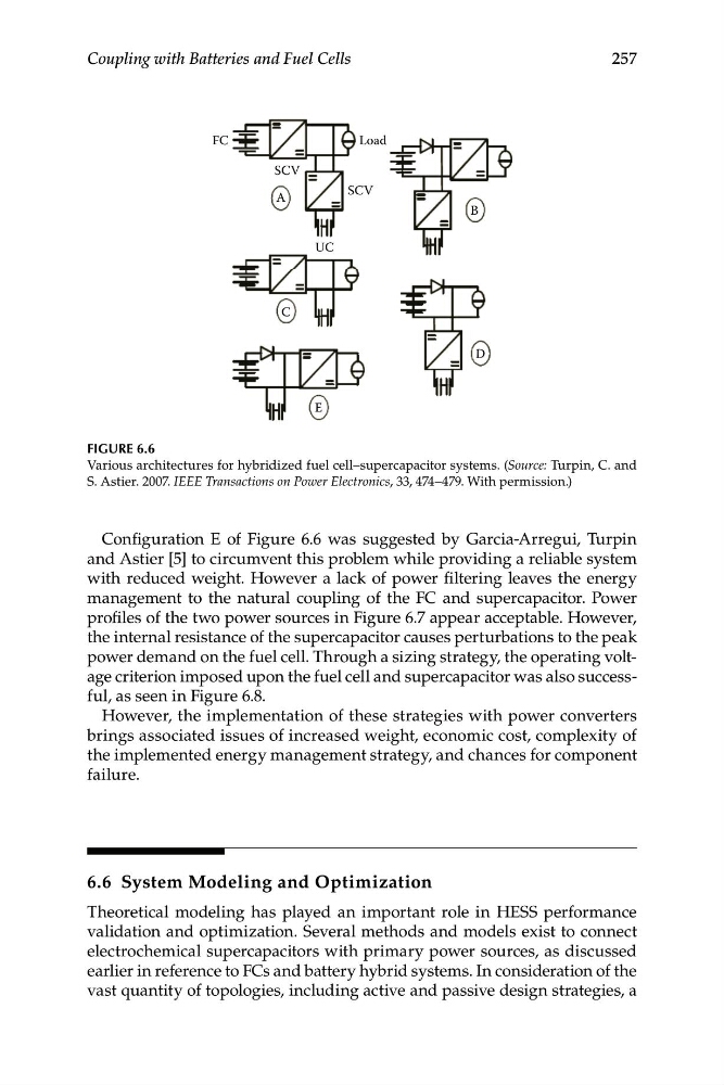
FIGURE 6.6
Various architectures for hybridized fuel cell–supercapacitor systems. (Source: Turpin, C. and
S. Astier. 2007. IEEE Transactions on Power Electronics, 33, 474–479. With permission.)
Configuration E of Figure 6.6 was suggested by Garcia-Arregui, Turpin
and Astier [5] to circumvent this problem while providing a reliable system
with reduced weight. However a lack of power filtering leaves the energy
management to the natural coupling of the FC and supercapacitor. Power
profiles of the two power sources in Figure 6.7 appear acceptable. However,
the internal resistance of the supercapacitor causes perturbations to the peak
power demand on the fuel cell. Through a sizing strategy, the operating voltage criterion imposed upon the fuel cell and supercapacitor was also successful, as seen in Figure 6.8.
However, the implementation of these strategies with power converters
brings associated issues of increased weight, economic cost, complexity of
the implemented energy management strategy, and chances for component
failure.
6.6 System Modeling and Optimization
Theoretical modeling has played an important role in HESS performance
validation and optimization. Several methods and models exist to connect
electrochemical supercapacitors with primary power sources, as discussed
earlier in reference to FCs and battery hybrid systems. In consideration of the
vast quantity of topologies, including active and passive design strategies, a
Coupling with Batteries and Fuel Cells
FC
A
C
E
D
B
SCV
SCV
UC
Load
FIGURE 6.6
Various architectures for hybridized fuel cell–supercapacitor systems. (Source: Turpin, C. and
S. Astier. 2007. IEEE Transactions on Power Electronics, 33, 474–479. With permission.)
Configuration E of Figure 6.6 was suggested by Garcia-Arregui, Turpin
and Astier [5] to circumvent this problem while providing a reliable system
with reduced weight. However a lack of power filtering leaves the energy
management to the natural coupling of the FC and supercapacitor. Power
profiles of the two power sources in Figure 6.7 appear acceptable. However,
the internal resistance of the supercapacitor causes perturbations to the peak
power demand on the fuel cell. Through a sizing strategy, the operating voltage criterion imposed upon the fuel cell and supercapacitor was also successful, as seen in Figure 6.8.
However, the implementation of these strategies with power converters
brings associated issues of increased weight, economic cost, complexity of
the implemented energy management strategy, and chances for component
failure.
6.6 System Modeling and Optimization
Theoretical modeling has played an important role in HESS performance
validation and optimization. Several methods and models exist to connect
electrochemical supercapacitors with primary power sources, as discussed
earlier in reference to FCs and battery hybrid systems. In consideration of the
vast quantity of topologies, including active and passive design strategies, a