

256
Electrochemical Supercapacitors for Energy Storage and Delivery
avoid these phenomena and increase the expected lifetime of a PEMFC,
control limitations must be set to the current supplied by the system. As a
main energy source similar to batteries for high power applications, an FC
can provide continual energy to power operations for extended periods but
there remains an obvious need for a fast auxiliary power source necessary to
improve the overall system performance.
HESS coupling of ES to FC is done to exploit the ability of the former to
respond to rapid increases in power demand. The extended lifetime of a
supercapacitor is also useful in meeting a PEMFC objective to minimize
required maintenance. Once more, various architectures are possible with
this hybrid system, with each possessing benefits and detriments that largely
depend on the resulting applications.
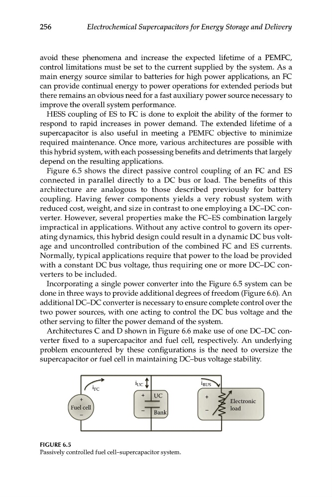
Figure 6.5 shows the direct passive control coupling of an FC and ES
connected in parallel directly to a DC bus or load. The benefits of this
architecture are analogous to those described previously for battery
coupling. Having fewer components yields a very robust system with
reduced cost, weight, and size in contrast to one employing a DC–DC converter. However, several properties make the FC–ES combination largely
impractical in applications. Without any active control to govern its operating dynamics, this hybrid design could result in a dynamic DC bus voltage and uncontrolled contribution of the combined FC and ES currents.
Normally, typical applications require that power to the load be provided
with a constant DC bus voltage, thus requiring one or more DC–DC converters to be included.
Incorporating a single power converter into the Figure 6.5 system can be
done in three ways to provide additional degrees of freedom (Figure 6.6). An
additional DC–DC converter is necessary to ensure complete control over the
two power sources, with one acting to control the DC bus voltage and the
other serving to filter the power demand of the system.
Architectures C and D shown in Figure 6.6 make use of one DC–DC converter fixed to a supercapacitor and fuel cell, respectively. An underlying
problem encountered by these configurations is the need to oversize the
supercapacitor or fuel cell in maintaining DC–bus voltage stability.
i FC
i UC
UC
Bank
Fuel cell
+
–
+
–
+
–
Electronic
load
i BUS
FIGURE 6.5
Passively controlled fuel cell–supercapacitor system.
Electrochemical Supercapacitors for Energy Storage and Delivery
avoid these phenomena and increase the expected lifetime of a PEMFC,
control limitations must be set to the current supplied by the system. As a
main energy source similar to batteries for high power applications, an FC
can provide continual energy to power operations for extended periods but
there remains an obvious need for a fast auxiliary power source necessary to
improve the overall system performance.
HESS coupling of ES to FC is done to exploit the ability of the former to
respond to rapid increases in power demand. The extended lifetime of a
supercapacitor is also useful in meeting a PEMFC objective to minimize
required maintenance. Once more, various architectures are possible with
this hybrid system, with each possessing benefits and detriments that largely
depend on the resulting applications.
Figure 6.5 shows the direct passive control coupling of an FC and ES
connected in parallel directly to a DC bus or load. The benefits of this
architecture are analogous to those described previously for battery
coupling. Having fewer components yields a very robust system with
reduced cost, weight, and size in contrast to one employing a DC–DC converter. However, several properties make the FC–ES combination largely
impractical in applications. Without any active control to govern its operating dynamics, this hybrid design could result in a dynamic DC bus voltage and uncontrolled contribution of the combined FC and ES currents.
Normally, typical applications require that power to the load be provided
with a constant DC bus voltage, thus requiring one or more DC–DC converters to be included.
Incorporating a single power converter into the Figure 6.5 system can be
done in three ways to provide additional degrees of freedom (Figure 6.6). An
additional DC–DC converter is necessary to ensure complete control over the
two power sources, with one acting to control the DC bus voltage and the
other serving to filter the power demand of the system.
Architectures C and D shown in Figure 6.6 make use of one DC–DC converter fixed to a supercapacitor and fuel cell, respectively. An underlying
problem encountered by these configurations is the need to oversize the
supercapacitor or fuel cell in maintaining DC–bus voltage stability.
i FC
i UC
UC
Bank
Fuel cell
+
–
+
–
+
–
Electronic
load
i BUS
FIGURE 6.5
Passively controlled fuel cell–supercapacitor system.