

ΔT
–0.4
–0.3
Temperature deviation comparison
at 5 min
–0.2
–0.1
0
0.1
0.2
0.3
0.4
T-Tavg [°C]
0.1
3.25°C
Y[m]
0.05
0
0.2
0.4
0.6
0.8
1
1.2
1.4
1.6
1.8
2
X[m]
2 tabs
0.1
0.78°C
0.37°C
0.19°C
Y[m]
Y[m]
Y[m]
Y[m]
Y[m]
Y[m]
Y[m]
0.05
0
0.2
0.4
0.6
0.8
1
1.2
1.4
1.6
1.8
2
X[m]
5 tabs
0.1
0.05
0
0.2
0.4
0.6
0.8
1
1.2
1.4
1.6
1.8
2
X[m]
10 tabs
0.1
0.05
0
0.2
0.4
0.6
0.8
1
1.2
1.4
1.6
1.8
2
X[m]
Continuous tab
(a)
Electrochemical reaction rate comparison
in the inner electrode pair at 5 min
i” [A/m 2 ]
120
121
122
123
124
125
126
127
128
129
130
Δi”/i”avg
0.1
32.2%
6.6%
2.2%
0.2%
0.05
0
0.2
0.4
0.6
0.8
1
1.2
1.4
1.6
1.8
2
X[m]
2 tabs
0.1
0.05
0
0.2
0.4
0.6
0.8
1
1.2
1.4
1.6
1.8
2
X[m]
5 tabs
0.1
0.05
0
0.2
0.4
0.6
0.8
1
1.2
1.4
1.6
1.8
2
X[m]
10 tabs
0.1
0.05
0
0.2
0.4
0.6
0.8
1
1.2
1.4
1.6
1.8
2
X[m]
Continuous tab
(b)
Teflon body
Working
electrode
surface
Reference
electrode
Thermometer
Counter electrode
Pt
Glass frit
Vycor tip
Electrolyte
Working
electrode
N 2 gas purging
Purging gas outlet
Teflon body
Working
electrode
surface
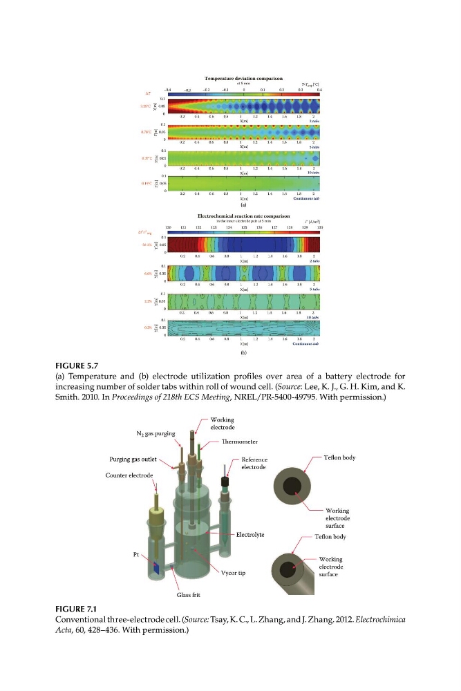
FIGURE 5.7
(a) Temperature and (b) electrode utilization profiles over area of a battery electrode for
increasing number of solder tabs within roll of wound cell. (Source: Lee, K. J., G. H. Kim, and K.
Smith. 2010. In Proceedings of 218th ECS Meeting, NREL/PR-5400-49795. With permission.)
FIGURE 7.1
Conventional three-electrode cell. (Source: Tsay, K. C., L. Zhang, and J. Zhang. 2012. Electrochimica
Acta, 60, 428–436. With permission.)
–0.4
–0.3
Temperature deviation comparison
at 5 min
–0.2
–0.1
0
0.1
0.2
0.3
0.4
T-Tavg [°C]
0.1
3.25°C
Y[m]
0.05
0
0.2
0.4
0.6
0.8
1
1.2
1.4
1.6
1.8
2
X[m]
2 tabs
0.1
0.78°C
0.37°C
0.19°C
Y[m]
Y[m]
Y[m]
Y[m]
Y[m]
Y[m]
Y[m]
0.05
0
0.2
0.4
0.6
0.8
1
1.2
1.4
1.6
1.8
2
X[m]
5 tabs
0.1
0.05
0
0.2
0.4
0.6
0.8
1
1.2
1.4
1.6
1.8
2
X[m]
10 tabs
0.1
0.05
0
0.2
0.4
0.6
0.8
1
1.2
1.4
1.6
1.8
2
X[m]
Continuous tab
(a)
Electrochemical reaction rate comparison
in the inner electrode pair at 5 min
i” [A/m 2 ]
120
121
122
123
124
125
126
127
128
129
130
Δi”/i”avg
0.1
32.2%
6.6%
2.2%
0.2%
0.05
0
0.2
0.4
0.6
0.8
1
1.2
1.4
1.6
1.8
2
X[m]
2 tabs
0.1
0.05
0
0.2
0.4
0.6
0.8
1
1.2
1.4
1.6
1.8
2
X[m]
5 tabs
0.1
0.05
0
0.2
0.4
0.6
0.8
1
1.2
1.4
1.6
1.8
2
X[m]
10 tabs
0.1
0.05
0
0.2
0.4
0.6
0.8
1
1.2
1.4
1.6
1.8
2
X[m]
Continuous tab
(b)
Teflon body
Working
electrode
surface
Reference
electrode
Thermometer
Counter electrode
Pt
Glass frit
Vycor tip
Electrolyte
Working
electrode
N 2 gas purging
Purging gas outlet
Teflon body
Working
electrode
surface
FIGURE 5.7
(a) Temperature and (b) electrode utilization profiles over area of a battery electrode for
increasing number of solder tabs within roll of wound cell. (Source: Lee, K. J., G. H. Kim, and K.
Smith. 2010. In Proceedings of 218th ECS Meeting, NREL/PR-5400-49795. With permission.)
FIGURE 7.1
Conventional three-electrode cell. (Source: Tsay, K. C., L. Zhang, and J. Zhang. 2012. Electrochimica
Acta, 60, 428–436. With permission.)