

214
Electrochemical Supercapacitors for Energy Storage and Delivery
(a)
(b)
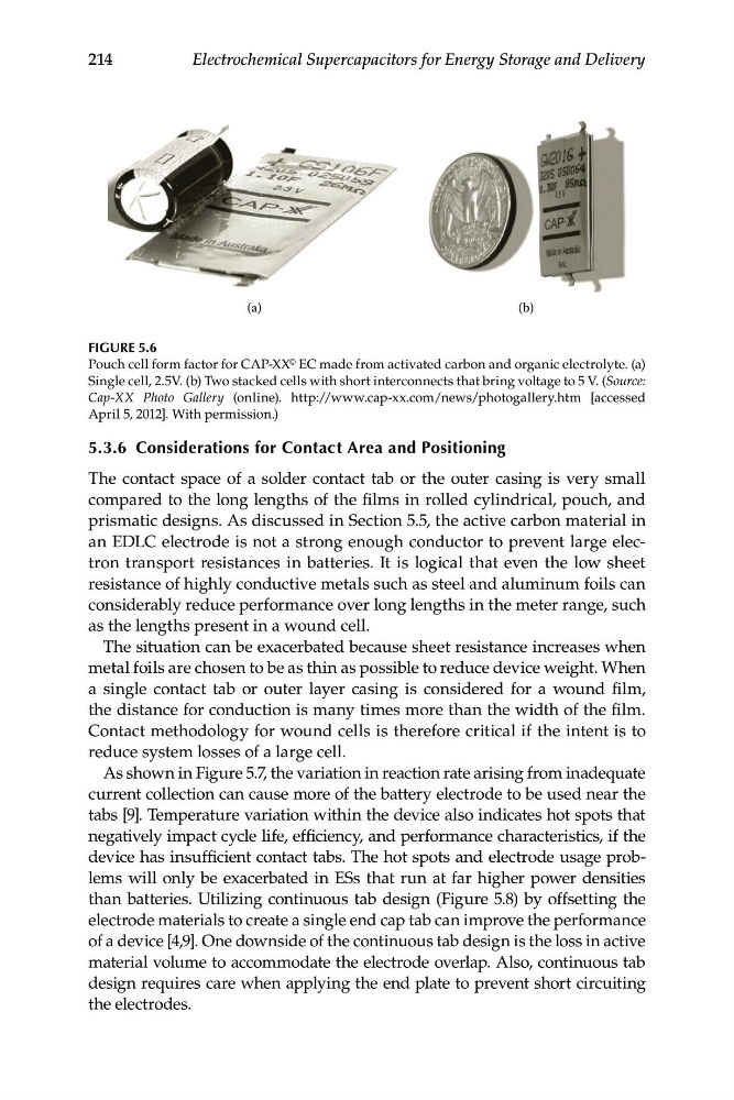
FIGURE 5.6
Pouch cell form factor for CAP-XX © EC made from activated carbon and organic electrolyte. (a)
Single cell, 2.5V. (b) Two stacked cells with short interconnects that bring voltage to 5 V. (Source:
Cap-XX Photo Gallery (online). http://www.cap-xx.com/news/photogallery.htm [accessed
April 5, 2012]. With permission.)
5.3.6 Considerations for Contact Area and Positioning
The contact space of a solder contact tab or the outer casing is very small
compared to the long lengths of the films in rolled cylindrical, pouch, and
prismatic designs. As discussed in Section 5.5, the active carbon material in
an EDLC electrode is not a strong enough conductor to prevent large electron transport resistances in batteries. It is logical that even the low sheet
resistance of highly conductive metals such as steel and aluminum foils can
considerably reduce performance over long lengths in the meter range, such
as the lengths present in a wound cell.
The situation can be exacerbated because sheet resistance increases when
metal foils are chosen to be as thin as possible to reduce device weight. When
a single contact tab or outer layer casing is considered for a wound film,
the distance for conduction is many times more than the width of the film.
Contact methodology for wound cells is therefore critical if the intent is to
reduce system losses of a large cell.
As shown in Figure 5.7, the variation in reaction rate arising from inadequate
current collection can cause more of the battery electrode to be used near the
tabs [9]. Temperature variation within the device also indicates hot spots that
negatively impact cycle life, efficiency, and performance characteristics, if the
device has insufficient contact tabs. The hot spots and electrode usage problems will only be exacerbated in ESs that run at far higher power densities
than batteries. Utilizing continuous tab design (Figure 5.8) by offsetting the
electrode materials to create a single end cap tab can improve the performance
of a device [4,9]. One downside of the continuous tab design is the loss in active
material volume to accommodate the electrode overlap. Also, continuous tab
design requires care when applying the end plate to prevent short circuiting
the electrodes.
Electrochemical Supercapacitors for Energy Storage and Delivery
(a)
(b)
FIGURE 5.6
Pouch cell form factor for CAP-XX © EC made from activated carbon and organic electrolyte. (a)
Single cell, 2.5V. (b) Two stacked cells with short interconnects that bring voltage to 5 V. (Source:
Cap-XX Photo Gallery (online). http://www.cap-xx.com/news/photogallery.htm [accessed
April 5, 2012]. With permission.)
5.3.6 Considerations for Contact Area and Positioning
The contact space of a solder contact tab or the outer casing is very small
compared to the long lengths of the films in rolled cylindrical, pouch, and
prismatic designs. As discussed in Section 5.5, the active carbon material in
an EDLC electrode is not a strong enough conductor to prevent large electron transport resistances in batteries. It is logical that even the low sheet
resistance of highly conductive metals such as steel and aluminum foils can
considerably reduce performance over long lengths in the meter range, such
as the lengths present in a wound cell.
The situation can be exacerbated because sheet resistance increases when
metal foils are chosen to be as thin as possible to reduce device weight. When
a single contact tab or outer layer casing is considered for a wound film,
the distance for conduction is many times more than the width of the film.
Contact methodology for wound cells is therefore critical if the intent is to
reduce system losses of a large cell.
As shown in Figure 5.7, the variation in reaction rate arising from inadequate
current collection can cause more of the battery electrode to be used near the
tabs [9]. Temperature variation within the device also indicates hot spots that
negatively impact cycle life, efficiency, and performance characteristics, if the
device has insufficient contact tabs. The hot spots and electrode usage problems will only be exacerbated in ESs that run at far higher power densities
than batteries. Utilizing continuous tab design (Figure 5.8) by offsetting the
electrode materials to create a single end cap tab can improve the performance
of a device [4,9]. One downside of the continuous tab design is the loss in active
material volume to accommodate the electrode overlap. Also, continuous tab
design requires care when applying the end plate to prevent short circuiting
the electrodes.